Cisco WS-X4624-SFP-E Hardware Maintenance Manual - Page 43
available for the two versions of serial modules: both DTE and DCE versions of V.35, EIA/TIA-232
 |
UPC - 882658134944
View all Cisco WS-X4624-SFP-E manuals
Add to My Manuals
Save this manual to your list of manuals |
Page 43 highlights
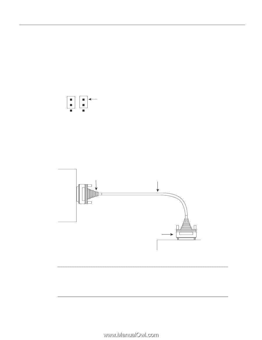
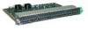
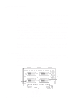
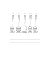
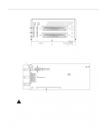
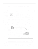
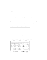
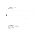
Network Connection Considerations If the network processor module is operating as DTE in NRZI mode, the sense of the dte-invert-timing command must be manually changed. For instance, if the command no dte-invert-timing was previously entered in the configuration file, then dte-invert-timing must be configured for the module to operate as DTE in NRZI mode. To set the jumpers for NRZI, move the jumpers to the position shown in Figure 2-22 using the orientation shown in Figure 2-21. Figure 2-22 Dual Serial Network Processor Module Jumpers, J4 and J5-NRZI Setting J5 J4 Pin 1 H1125a Port 1 Port 0 You must use a special serial cable to connect the router to a modem, CSU/DSU, or other device as shown in Figure 2-23. This cable, available from your customer service representative, is normally ordered with the system. See the appendix "Cabling Specifications." Nine different serial cables are available for the two versions of serial modules: both DTE and DCE versions of V.35, EIA/TIA-232, EIA/TIA-449, and X.21; and EIA-530 DTE. Note that the cables for the two versions are not interchangeable. Figure 2-23 Router Serial Cable Connections Serial port 50-pin connector Serial transition cable Chassis H1037a EIA/TIA-232, EIA/TIA-449, V.35, X.21, or EIA-530 connector Modem or CSU/DSU Note Serial ports configured as DCE must also be configured with the clockrate command. An error message will be generated if there is a mismatch between the cable and the software configuration of the port-for example, if the cable is DTE and the clock rate is set, or if the cable is DCE and the clock rate is not configured. For more information on software commands, refer to the software publications. Preparing for Installation 2-21
-
 1
1 -
2
-
3
-
4
-
5
-
6
-
7
-
8
-
9
-
10
-
11
-
12
-
13
-
14
-
15
-
16
-
17
-
18
-
19
-
20
-
21
-
22
-
23
-
24
-
25
-
26
-
27
-
28
-
29
-
30
-
31
-
32
-
33
-
34
-
35
-
36
-
37
-
 38
38 -
 39
39 -
 40
40 -
 41
41 -
 42
42 -
 43
43 -
 44
44 -
 45
45 -
 46
46 -
 47
47 -
 48
48 -
49
-
50
-
51
-
52
-
53
-
54
-
55
-
56
-
57
-
58
-
59
-
60
-
61
-
62
-
63
-
64
-
65
-
66
-
67
-
68
-
69
-
70
-
71
-
72
-
73
-
74
-
75
-
76
-
77
-
78
-
79
-
80
-
81
-
82
-
83
-
84
-
85
-
86
-
87
-
88
-
89
-
90
-
91
-
92
-
93
-
94
-
95
-
96
-
97
-
98
-
99
-
100
-
101
-
102
-
103
-
104
-
105
-
106
-
107
-
108
-
109
-
110
-
111
-
112
-
113
-
114
-
115
-
116
-
117
-
118
-
119
-
120
-
121
-
122
-
123
-
124
-
125
-
126
-
127
-
128
-
129
-
130
-
131
-
132
-
133
-
134
-
135
-
136
-
137
-
138
-
139
-
140
-
141
-
142
-
143
 |
 |