Cisco WS-X4624-SFP-E Hardware Maintenance Manual - Page 54
Channelized E1 Connections, CE1 Jumper Settings
 |
UPC - 882658134944
View all Cisco WS-X4624-SFP-E manuals
Add to My Manuals
Save this manual to your list of manuals |
Page 54 highlights
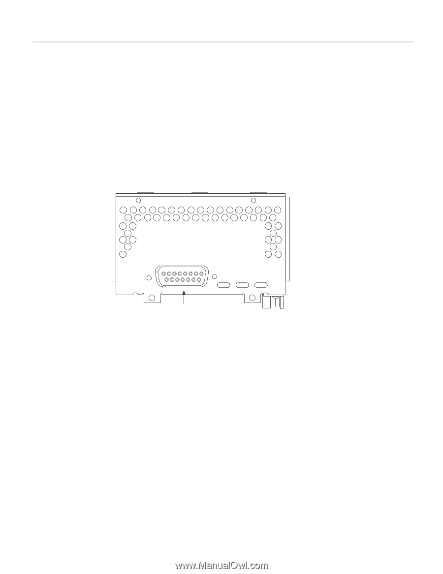
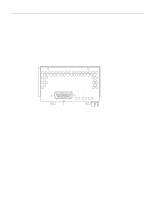
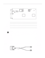
LOOPBACK LOCAL ALARM REMOTE ALARM H3154 Network Connection Considerations Channelized E1 Connections The Cisco 4000 series router supports a channelized E1 (CE1) network processor module with one E1 interface.The CE1 provides one channelized E1 connection via a serial cable to a channel service unit (CSU). On the CE1, the controller provides up to 24 virtual channels. Each virtual channel is presented to the system as a serial interface that can be configured individually. This interface is the physical media that supports ISDN PRI. The CE1, shown in Figure 2-34, provides a controller for transmitting and receiving data bidirectionally at the E1 rate of 2.048 Mbps. For wide-area networking, the CE1 can function as a concentrator for a remote site. Figure 2-34 Channelized E1 Network Interface Processor cE1 / PRI DB-15 female Following are the E1 specifications: • Transmission bit rate: 2.048 Mbps ± 50 ppm • Output port specifications: see G.703 / Section 6.3 (CCITT specification) • Input port specifications: see G.703 / Section 6.3 (CCITT specification) • Jitter attenuation starting at 6 hertz (Hz), which meets or exceeds G.823 for E1 CE1 Jumper Settings The jumpers on the CE1 module set capacitive coupling between the transmit or receive shield and chassis ground, and the cable resistance (120-ohm or 75-ohm). By default, the CE1 module is set with capacitive coupling between the receive (Rx) shield and chassis ground. This provides direct current (DC) isolation between the chassis and external devices, as stated in the G.703 specification. Jumper J2 (see Figure 2-35) controls this function. To set capacitive coupling between the transmit (Tx) shield and chassis ground, set jumper J2 as described in Table 2-7. Figure 2-35 also shows the location of jumpers J1, J3, J4, J5, and J7. These jumpers set the cable impedance to 120-ohm or 75-ohm. The figure shows the cable impedance set to 120-ohm. 2-32 Cisco 4000 Series Hardware Installation and Maintenance
-
 1
1 -
2
-
3
-
4
-
5
-
6
-
7
-
8
-
9
-
10
-
11
-
12
-
13
-
14
-
15
-
16
-
17
-
18
-
19
-
20
-
21
-
22
-
23
-
24
-
25
-
26
-
27
-
28
-
29
-
30
-
31
-
32
-
33
-
34
-
35
-
36
-
37
-
38
-
39
-
40
-
41
-
42
-
43
-
44
-
45
-
46
-
47
-
48
-
 49
49 -
 50
50 -
 51
51 -
 52
52 -
 53
53 -
 54
54 -
 55
55 -
 56
56 -
 57
57 -
 58
58 -
 59
59 -
60
-
61
-
62
-
63
-
64
-
65
-
66
-
67
-
68
-
69
-
70
-
71
-
72
-
73
-
74
-
75
-
76
-
77
-
78
-
79
-
80
-
81
-
82
-
83
-
84
-
85
-
86
-
87
-
88
-
89
-
90
-
91
-
92
-
93
-
94
-
95
-
96
-
97
-
98
-
99
-
100
-
101
-
102
-
103
-
104
-
105
-
106
-
107
-
108
-
109
-
110
-
111
-
112
-
113
-
114
-
115
-
116
-
117
-
118
-
119
-
120
-
121
-
122
-
123
-
124
-
125
-
126
-
127
-
128
-
129
-
130
-
131
-
132
-
133
-
134
-
135
-
136
-
137
-
138
-
139
-
140
-
141
-
142
-
143
 |
 |