Cisco WS-X6148-GE-TX Hardware Installation Guide - Page 56
Replacing or Installing Components, Replacing or Installing Expansion Modules
 |
UPC - 746320802060
View all Cisco WS-X6148-GE-TX manuals
Add to My Manuals
Save this manual to your list of manuals |
Page 56 highlights
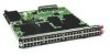
Replacing or Installing Components Chapter 2 Installing the Cisco UCS 6100 Series Fabric Interconnect Send document comments to [email protected] Step 14 Power up, connect the terminal to the console port, and configure the secondary fabric interconnect as descrubed in the Configuration guide for your software release. The procedure is in the "System Configuration" section, "Configuring the Fabric Interconnects" chapter. Note A setup utility launches automatically the first time you access the system and guides you through the basic configuration. For instructions on how to configure the system and check module connectivity, see the Cisco UCS Manager CLI Configuration Guide or theCisco UCS Manager GUI Configuration Guide . Replacing or Installing Components This section describes how to replace and install components, and contains the following topics: • Replacing or Installing Expansion Modules, page 2-22 • Replacing or Installing Power Supplies, page 2-24 • Replacing a Fan Module, page 2-27 • Removing a Cisco UCS 6120XP, page 2-29 Caution To prevent ESD damage, wear grounding wrist straps during these procedures and handle modules by the carrier edges only. Replacing or Installing Expansion Modules You can either replace existing expansion modules or install new ones where expansion modules are not installed. If you are replacing a module, you need to follow the procedures that explain how to remove and install expansion modules. If you are installing an expansion module, you need to follow only the installation procedure. Caution To prevent ESD damage, wear grounding wrist straps during these procedures. When handling the expansion modules, handle them only on their carrier edges. Note Install the Cisco UCS 6100 Series Fabric Interconnect chassis in the rack before installing expansion modules. For information about installing the chassis, see the "Installing the Cisco UCS 6120XP Chassis in a Cabinet or Rack" section on page 2-6. This section includes the following topics: • Removing an Expansion Module, page 2-23 • Installing an Expansion Module, page 2-24 2-22 Cisco UCS 6100 Series Fabric Interconnect Hardware Installation Guide OL-20036-02
-
 1
1 -
2
-
3
-
4
-
5
-
6
-
7
-
8
-
9
-
10
-
11
-
12
-
13
-
14
-
15
-
16
-
17
-
18
-
19
-
20
-
21
-
22
-
23
-
24
-
25
-
26
-
27
-
28
-
29
-
30
-
31
-
32
-
33
-
34
-
35
-
36
-
37
-
38
-
39
-
40
-
41
-
42
-
43
-
44
-
45
-
46
-
47
-
48
-
49
-
50
-
 51
51 -
 52
52 -
 53
53 -
 54
54 -
 55
55 -
 56
56 -
 57
57 -
 58
58 -
 59
59 -
 60
60 -
 61
61 -
62
-
63
-
64
-
65
-
66
-
67
-
68
-
69
-
70
-
71
-
72
-
73
-
74
-
75
-
76
-
77
-
78
-
79
-
80
-
81
-
82
-
83
-
84
-
85
-
86
-
87
-
88
-
89
-
90
-
91
-
92
-
93
-
94
-
95
-
96
 |
 |
