Coby DTV 102 User Manual - Page 3
Board Level Description, Connectors - ir code
 |
UPC - 716829971024
View all Coby DTV 102 manuals
Add to My Manuals
Save this manual to your list of manuals |
Page 3 highlights
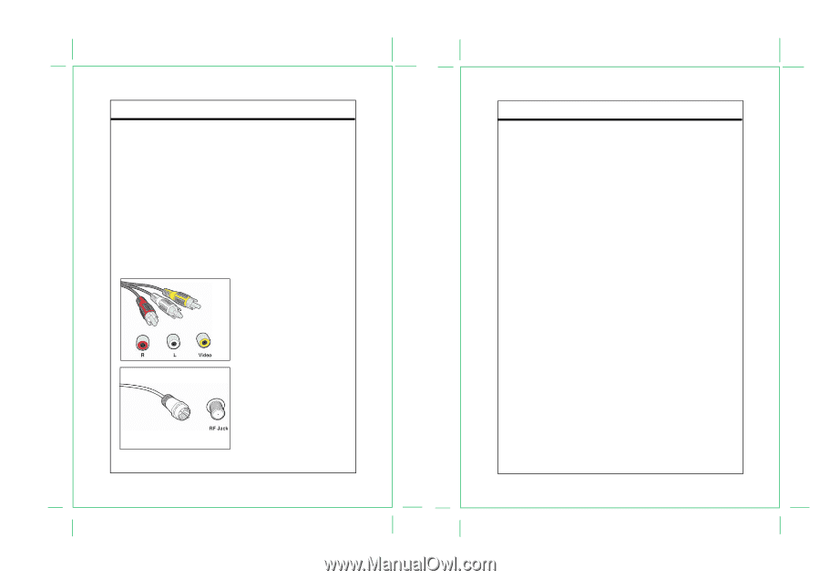
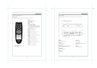
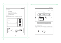
Introduction 1.3 Board Level Description The DTV-102 supports one input and two outputs. The input is a standard RF connector, which can be connected to an antenna with a coaxial cable. The outputs are standard NTSC composite video and left/right audio outputs, with RCA jack connectors, and a standard RF output; both are provided to insure an easy connection to any analog TV. The RF output provides video modulated on Channel 3 or Channel 4, as selected by the on-board switch. The Audio/Video (A/V) cables provide good picture quality and stereo sound, and should be used if available on the TV. The A/V jacks are color coded (yellow for video, red for right audio and white for left audio). If the TV has only one input for audio (mono), connect it to the left (white) audio jack on the converter box (CB) . The RF jack and coaxial cable provide acceptable picture and mono sound quality. It should be used if A/V connections are not available on the TV. RF jacks are typically used to connect your TV to terrestrial antenna sources. Note: Be sure to use RG-6 coaxial cable when connecting from the antenna to the CB module. Introduction The module also includes an infra-red (IR) receiver and three push buttons to provide front panel control for the power on/off and channel up/down functions. The only one LED indicates three possible power states for the converter box: • Powered on and functional • In stand-by mode • Powered off Bright Green LED is ON Dim Red LED is ON Red LED is OFF. Figure1. Connectors - 3 - - 4 -
-
 1
1 -
 2
2 -
 3
3 -
 4
4 -
 5
5 -
 6
6 -
 7
7 -
 8
8 -
 9
9 -
10
-
11
-
12
-
13
-
14
-
15
-
16
-
17
-
18
 |
 |