Coby DTV 102 User Manual - Page 5
Installation - converter
 |
UPC - 716829971024
View all Coby DTV 102 manuals
Add to My Manuals
Save this manual to your list of manuals |
Page 5 highlights
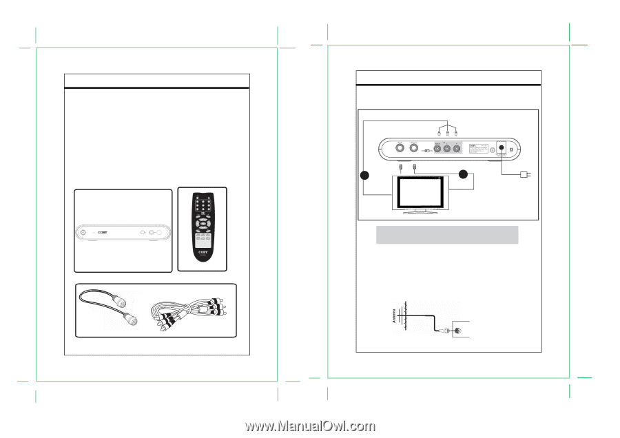
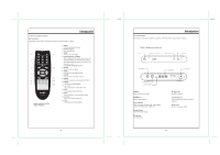
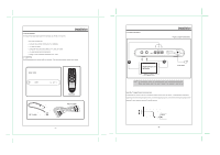
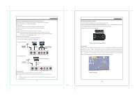
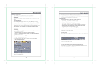
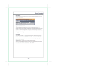
2.1 Setup Checklist The required hardware and equipment necessary to use the DTV-102 are: Installation - DTV-102 converter box - Converter box remote control and 2 AAA batteries - RF cable for output - Composite video and audio cables, or RF cable, for output - RF video source (terrestrial antenna) - Analog TV with composite video/audio or RF input 2.2 Unpacking The following items are included with your product. If any items are missing, contact your dealer. Main Unit RF Cable Remote RCA Cable - 7 - 2.3 Cabel Connections Installation Figure 4. Cable Connections A B MONITOR WITH AV /RF INPUT To Wall Outlet NOTE: Set the external receiver to the relative input mode to enable the signal pass. When output signal, refer to the user's manual of the external receiver as well. Input the TV signal to your converter box Connect the RF source to the RF IN connector located on the unit's rear panel. To view television channels, a signal must be received by the device from one of the following sources: The internal antenna/An outdoor aerial antenna/A cable television network/A satellite network. RF IN - 8 -
-
 1
1 -
 2
2 -
 3
3 -
 4
4 -
 5
5 -
 6
6 -
 7
7 -
 8
8 -
 9
9 -
 10
10 -
 11
11 -
12
-
13
-
14
-
15
-
16
-
17
-
18
 |
 |