Craftsman 16636 Owners Manual - Page 5
Parts & Features - tools
 |
View all Craftsman 16636 manuals
Add to My Manuals
Save this manual to your list of manuals |
Page 5 highlights
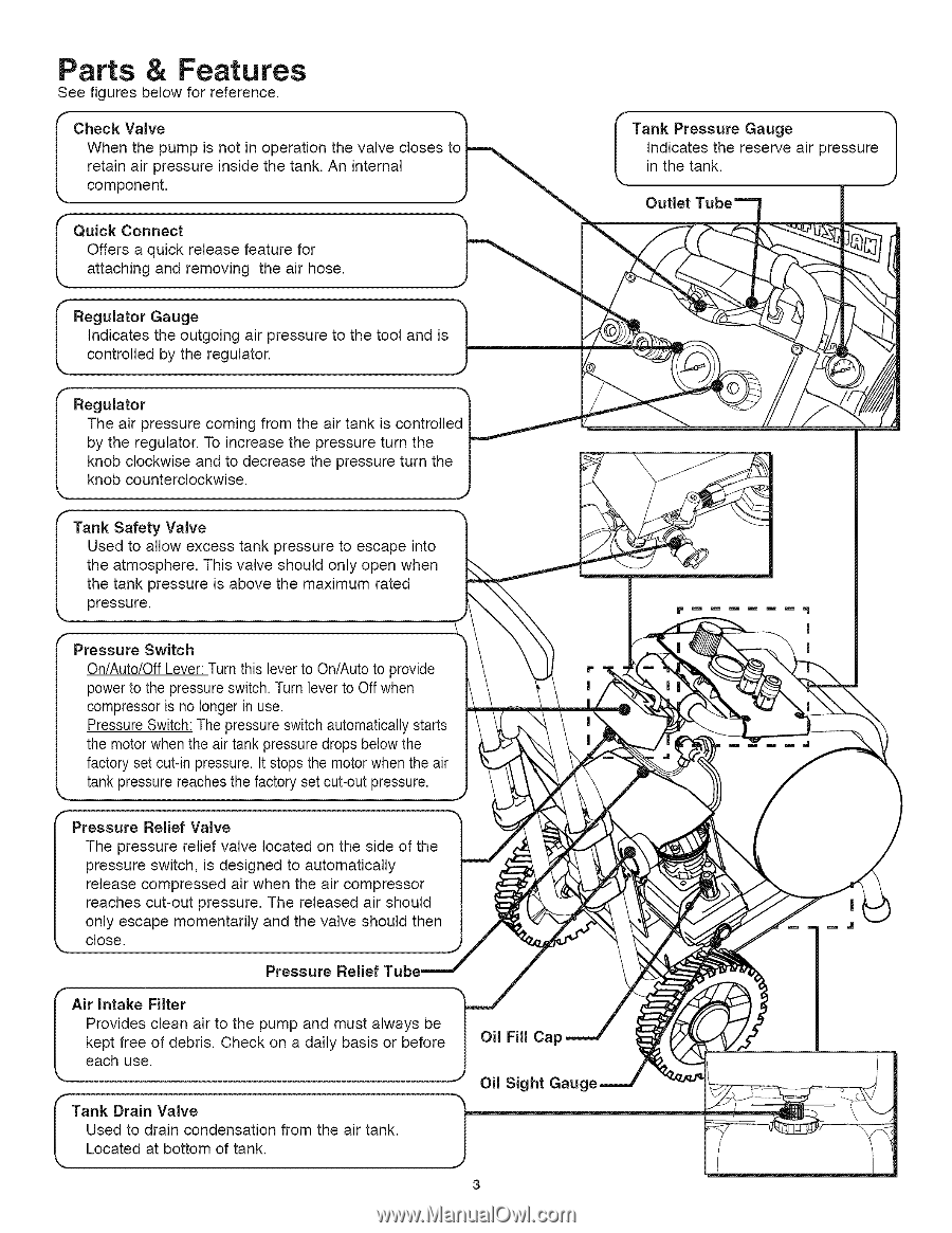
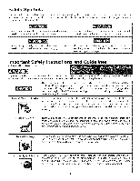
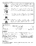
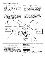
Parts & Features See figures below for reference. When the pump is not in operation the valve closes t I ChrceeoctmakipnoVnaaeirlvnept.ressure inside the tank. An internal Jo|'_ Offers a quick release feature for I QuaitctkachiCnognneacntd removing the air hose. Indicates the outgoing air pressure to the tool and is I Recgounlatrtoollred Gbayugthee regulator. I Regulator "_ The air pressure coming from the air tank is controlled I by the regulator. To increase the pressure turn the r_ knob clockwise and to decrease the pressure turn the knob counterclockwise. Tank Safety Valve Used to allow excess tank pressure to escape into the atmosphere. This valve should only open when the tank pressure is above the maximum rated pressure. Pressure Switch On/Auto/Off Lever: Turn this lever to On/Auto to provide power to the pressure switch. Turn lever to Off when compressor is no longer in use. Pressure Switch: The pressure switch automatically starts the motor when the air tank pressure drops below the factory set cut-in pressure. It stops the motor when the air tank pressure reaches the factory set cut-out pressure. Pressure Relief Valve The pressure relief valve located on the side of the pressure switch, is designed to automatically release compressed air when the air compressor reaches cut-out pressure. The released air should only escape momentarily and the valve should then close. Pressure Relief Air Intake Filter Provides clean air to the pump and must always be kept free of debris. Check on a daily basis or before each use. Tank Drain Valve Used to drain condensation from the air tank. Located at bottom of tank. f Tank Pressure Gauge Indicates the reserve air pressure in the tank.
-
 1
1 -
 2
2 -
 3
3 -
 4
4 -
 5
5 -
 6
6 -
 7
7 -
 8
8 -
 9
9 -
 10
10 -
 11
11 -
12
-
13
-
14
-
15
-
16
-
17
-
18
-
19
-
20
-
21
-
22
-
23
-
24
-
25
-
26
-
27
-
28
 |
 |