Craftsman 21400 Owners Manual - Page 7
c.Setthebladeguide
 |
View all Craftsman 21400 manuals
Add to My Manuals
Save this manual to your list of manuals |
Page 7 highlights
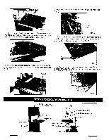
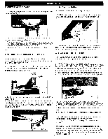
a.Removteheripfencet,heguiderail,thewingnutandscrew fromthetable. bkn.Oopbes.ntheuppear ndlowedr oorsbytumingthedoorlocking c.Loosetnhebladetensiobnyturnintghebladetensionknobon thetopoftheuppewr heehl ousincgounterclockwuinsteilthesaw bladehasslackene(dviewefdromabove()SeeFig.12). c. Setthebladeguidetotherequirehdeighbt yturnintgheguide postadjustinkgnob. d. Tightetnhewingnutaftersetting. Guide post adjusting knob FIG. 14 8. ADJUSTING THE BLADE GUIDES d. Remove the saw blade from the upper and lower wheels. e. When fitting the new saw blade ensure the blade teeth are pointing downwards and towards you at the position where the saw blade passes through the table. f. Re-tension the new saw blade and check the saw blade tracking by turning the upper wheel by hand. The saw blade should run in the center of the bandsaw wheels. g. If need adjust the tracking of the saw blade, proceed as mentioned below" TRACKING THE SAW BLADE" h. Replace the rip fence, the guide rail, the wing nut and screw to the table. i. Close the upper and lower doors by turning the door locking knobs before reconnecting the power supply. 6. TRACKING THE BANDSAW BLADE Set the tracking of the saw blade before setting the blade guides. Once the saw blade is installed and tensioned, track the saw blade by adjusting the tracking knob by hand (See Fig. 13). The saw blade should run in the center of the bandsaw wheels. When the correct adjustment is achieved lock the tracking knob with the wing nut. " I The Upper Blade Guide a. To adjust the upper blade guides, first position the right and left roller guides relative to the blade by slackening the ratcher handle Fig.15 and moving the guide carrier until both roller guides are approximately 1/16" behind the gullets of the saw blade. b. Set both roller guides to within 1/32" of the saw blade by releasing the guide adjusting screw (A) Fig. 15 on each side of the saw blade. Do not set the roller guides too close as this will adversely affect the life of the saw blade. c. Adjust the rear roller guide to be just clear of the back of the saw blade by unlocking the guide adjusting screw (B) Fig. 15 d. When the correct adjustment is reached, lock the rear roller guide in position with the guide adjusting screw (B) Fig.15 Guide adjusting screw (B) Ratchet handle I Guide adjusting screw (A) FIG, 15 The Lower Blade Guide Tracking knob I | FIG. 13 7. SETTING THE CUTTING HEIGHT a. The upper blade guide should be set as close as practical against the workpiece. b. To adjust this height, loosen the wing nut at the side of the upper wheel housing. (See Fig. 14) a. To adjust the lower blade guides, first position the right and left roller guides relative to the blade by slackening the lock nut Fig.16 and moving the guide carrier until both roller guides are approximately 1/16" behind the gullets of the saw blade b. Set both roller guides to within 1/32" of the saw blade by releasing the guide adjusting screw (C) Fig. 16 on each side of the saw blade. Do not set the roller guides too close as this will adversely affect the life of the saw blade. c. Adjust the rear roller guide to be just clear of the back of the saw blade by unlocking the guide adjusting screw (D) Fig, 16 7
-
 1
1 -
 2
2 -
 3
3 -
 4
4 -
 5
5 -
 6
6 -
 7
7 -
 8
8 -
 9
9 -
 10
10 -
 11
11 -
 12
12 -
13
-
14
-
15
-
16
-
17
-
18
-
19
-
20
 |
 |
