Craftsman 21513 Operation Manual - Page 3
Attach, Abrasive, Disc To Aluminum, Disc Table - parts
 |
View all Craftsman 21513 manuals
Add to My Manuals
Save this manual to your list of manuals |
Page 3 highlights
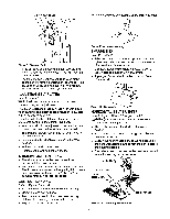
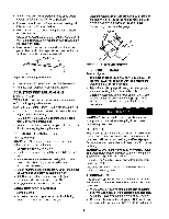
• Never stand on tool. Serious injury could occur if tool is tipped or if belt or disc are unintentionally contacted. • Know your tool. Learn the tool's operation, application and specific limitations, • Use recommended accessories (refer to page 13). Use of improper accessories may cause risk of injury to persons. • Handle workpiece correctly. Protect hands from possible injury. • Turn machine off if it jams. Belt jams when it digs too deeply into workpiece. (Motor force keeps it stuck in the work.) • Support workpiece with miter gauge, belt platen, work stop or work table. • Maintain '/_6"maximum clearance between table and sanding belt or disc. CAUTION; Think safety! Safety is a combination of operator common sense and alertness at all times when tool is being used. WARNING; Do not attempt to operate tool until it is completely assembled according to the instructions. ATTACH ABRASIVE DISC TO ALUMINUM DISC Refer to Figure 2. • Remove dust chute by looseningscrews and bolts, • Remove the adhesive cover from the back of the abrasive disc, I • Center abrasive on aluminumdisc and press to paste. • Make sure abrasive is pasted evenly on the aluminum disc. • Replace dust chute ATTACH DISC TABLE Refer to Figure 2, • Set the disc table at right angle to the aluminum disc i and secure the table position using two knobs and flat washers. Be sure that the gap between abrasive disc and disc table is _/_6o"r less. • Attach pointer to side of dust chute using 4-0,7 x 8mm socket head bolt from hardware bag. Adjust pointer to zero mark on trunnion and tighten bolt. AluminumDisc withAbrasive Refer to Figure 1. Check for shipping damage. If damage has occurred, a claim must be filed with the carrier for fastest action. Parts which need to be fastened to the unit should be located and accounted for: A Disc Table B Abrasive Disc C Miter Gauge Assembly D 1" Belt E Belt Table Parts bag (Part No. 21489.00) includes: horizontal stop bar, pointer, work stop, two knobs, one 10-1.50 x 25mm socket head bolt, one 4-0.7 x 8mm socket head bolt, one 10mm flat washer, two 6mm flat washers, one 81.25mm hex nut, one each 3, 5, 6, and 8ram hex wrenches and one extra long 3mm hex wrench. A -- .dc.--B C Knob FlatWasher .-" Pointer Disc'_able T_Jion _'X : Chute "_8_ "Screw Figure 2 - Secure Disc Table and Aluminum Disc ATTACH BELT TABLE Refer to Figure 3, • Attach belt table to left side of belt housing using the socket head bolt and flat washer from the hardware bag. • Set the belt table at right angle to the belt. • Be sure that gap between belt table and belt is '/16" or less. • Tighten socket head bolt to secure belt table position. Figure 1 - Unpacking Stop Bar Refer to Figures 2 and 3. CAUTION: Do not attempt assembly if parts are missing. Use operator's manual to order replacement parts. Figure 3 - Attach Belt Table 3 Belt Table Head Bolt
-
 1
1 -
 2
2 -
 3
3 -
 4
4 -
 5
5 -
 6
6 -
 7
7 -
 8
8 -
 9
9 -
10
-
11
-
12
-
13
-
14
-
15
-
16
-
17
-
18
-
19
-
20
-
21
-
22
-
23
-
24
 |
 |
