Craftsman 21513 Operation Manual - Page 4
Ati'ach, Horizontal - sander
 |
View all Craftsman 21513 manuals
Add to My Manuals
Save this manual to your list of manuals |
Page 4 highlights
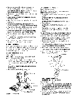
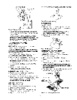
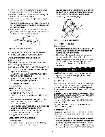
ATI'ACH HORIZONTAL STOP Refer to Figure 3, page 3. A horizontal stop bar with nut is provided as a positive stop when using the sander with the belt housing adjusted to a horizontal position. To attach stop bar: • Thread the horizontal stop bar into the threaded hole on the rear side of belt housing. • Tighten hex nut. Refer to Figures 4, 5 and 6, pages 4 and 5. POWER SOURCE WARNING: Do not connect sander to the power source until all assembly steps have been completed. The motor is designed for operation on the voltage and frequency specified. Normal loads will be handled safely on voltages not more than 10% above or below specified voltage. Running the unit on voltages which are not within range may cause overheating and motor burnout. Heavy loads require that voltage at motor terminals be no less than the voltage specified on nameplate. • Power supply to the motor is controlled by a single pole locking rocker switch. Remove the key to prevent unauthorized use. GROUNDING INSTRUCTIONS WARNING: improper connection of equipment grounding conductor can result in the risk of electrical shock. Equipment should be grounded while in use to protect operator from electrical shock. • Check with a qualified electrician if grounding instructions are not understood or if in doubt as to whether the tool is properly grounded. • This tool is equipped with an approved 3--conductor cord rated at 300V and a 3-prong grounding type plug (see Figure 4) for your protection against shock hazards. • Grounding plug should be plugged directly into a properly installed and grounded 3-prong groundingtype receptacle, as shown (Figure 4). Properly Grounded Outlet Grounding Prong 3-Prong Plug _._ Figure 4 - 3-Prong Receptacle • Do not remove or alter grounding prong in any man- ner. In the event of a malfunction or breakdown, grounding provides a path of least resistance for electrical shock. WARNING: Do not permit fingers to touch the terminals of plug when installingor removing from outlet. • Plug must be plugged into matching outlet that is properly installed and grounded in accordance with all local codes and ordinances. Do not modify plug provided. If it will not fit in outlet, have proper outlet installed by a qualified electrician. • Inspect tool cords periodically, and if damaged, have repaired by an authorized service facility. • Green (or green and yellow) conductor in cord is the grounding wire. If repair or replacement of the electric cord or plug is necessary, do not connect the green (or green and yellow) wire to a live terminal. • Where a 2-prong wall receptacle is encountered, it must be replaced with a properly grounded 3-prong receptacle installed in accordance with National Electric Code and local codes and ordinances. WARNING: This work should be performed by a qualified electrician. A temporary 3-prong to 2-prong grounding adapter (see Figure 5) is available for connecting plugs to a two pole outlet if it is properly grounded. Make Sure Grounding Lug _ 3-Prong Plug. \_ F====_ This Is I Connected To A Known | "-_ II Ground __ 2-Prong Receptacle Figure 5 - 2-Prong Receptacle with Adapter • DO not use a 3-prong to 2-prong groundingadapter unless permitted by local and national codes and ordinances. (A 3-prong to 2-prong grounding adapter is not permitted in Canada.) Where permitted, the rigid green tab or terminal on the side of the adapter must be securely connected to a permanent electrical ground such as a properly grounded water pipe, a properly grounded outlet box or a properly grounded wire system. • Many cover plate screws, water pipes and outlet boxes are not properly grounded. To ensure proper ground, grounding means must be tested by a qualified electrician. EXTENSION CORDS • The use of any extension cord will cause some drop in voltage and loss of power. • Wires of the extension cord must be of sufficient size to carry the current and maintain adequate voltage. • Use the table to determine the minimum wire size (A.W.G.) extension cord. • Use only 3-wire extension cords having 3-prong groundingtype plugs and 3-pole receptacles which accept the tool plug. • If the extensioncord is worn, cut, or damaged in any way,replace it immediately. 4
-
 1
1 -
 2
2 -
 3
3 -
 4
4 -
 5
5 -
 6
6 -
 7
7 -
 8
8 -
 9
9 -
 10
10 -
11
-
12
-
13
-
14
-
15
-
16
-
17
-
18
-
19
-
20
-
21
-
22
-
23
-
24
 |
 |
