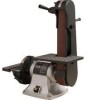
Craftsman 21513 Operation Manual - Page 6
Mount, Tracking, Abrasive
 |
View all Craftsman 21513 manuals
Add to My Manuals
Save this manual to your list of manuals |
Page 6 highlights
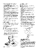
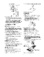
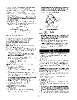
• Make sure abrasive belt always tracks properly. Correct tracking gives optimum performance. • After turning switch on, always allow belt to come up to full speed before sanding or grinding. • Be sure motor runs clockwise on disc side. Abrasive belt must travel down. • Avoid kickback by sanding in accordance with the directional arrows. • Keep your hands clear of abrasive belt, disc and all moving parts. • For optimum performance, do not stall motor or reduce speed. Do not force the work into the abrasive. • Support workpiece with belt table when sanding with belt, with disc table when sanding with disc. • Never push a sharp corner of the workpiece rapidly against the belt or disc. Abrasive backing may tear. • Replace abrasives when they become loaded (glazed) or frayed. • When grinding metal, move workpiece across abrasive to prevent heat buitt up. • Never attempt wet sanding. If the workpiece becomes too hot to handle, cool it in water. MOUNT SANDER During operation the sander may have a tendency to slide or move about on the bench or table. It is recommended to mount the sander onto a stand (see "Recommended Accessories", page 13) or to a bench top. ADJUSTING BELT TABLE Refer to Figure 7. WARNING: Disconnect sander from power source before making any adjustments. • To adjust belt table angle, loosen the socket head bolt and adjust table to desired angle. Use a combination square to set belt table at 45 ° or 90 ° from belt platen. • Adjust for '/,8" maximum clearance between the belt and the table. • Secure table position by tightening bolt. Socket Head Bolt REPLACING ABRASIVE Refer to Figures 7 and 8. BELT WARNING: Disconnect sander from power source before making any adjustments. • Sanding belt should be replaced when worn, torn, or glazed. • Loosen and remove two knobs from belt cover. • Remove belt cover. • Loosen and remove socket head bolt from bracket. • Remove bracket. • Loosen socket head bort and move belt table parallel to belt. • Release belt tension by pulling down on handle assembly. Slide old belt off the drive and tracking wheels. NOTE: There may be an arrow on the inside of the belt. The arrow should point in the direction of belt travel to ensure that the splice in the belt will not come apart. • Pull down on the handle and slide new belt over the drive and idler wheels. Center belt on wheels. • Rotate belt by hand to check tracking. Belt should ride centered on wheels. • If belt does not ride centered on wheers, adjust belt tracking as described in the next section. • Replace belt cover and secure it with two knobs. • Replace bracket and secure it with socket head bolt. • Reset belt table to be at the desired angle, and secure it by tightening the bolt. Idler Wheel Handle Figure 7 - Adjustments 'm_-Belt Platen ,_p.----Bracket _tHead Bo_t / "_r_socket Head Bolt Figure8 - ReplaceAbrasive Belt TRACKING ABRASIVE BELT Refer to Figure 9, page 7. • Test the tracking. Plug in power cord. Turn switch ON and immediately OFF. If the abrasive belt is centered on wheels and did not move to the right or left, it is tracking properly. If the belt moved to the right or left, adjustment is necessary. • To adjust the tracking wheel, loosen the locking nut on adjusting bolt. Use a 4mm hex wrench to turn adjusting bolt. 6
-
 1
1 -
 2
2 -
 3
3 -
 4
4 -
 5
5 -
 6
6 -
 7
7 -
 8
8 -
 9
9 -
 10
10 -
 11
11 -
 12
12 -
13
-
14
-
15
-
16
-
17
-
18
-
19
-
20
-
21
-
22
-
23
-
24
 |
 |
