Craftsman 21805 Operation Manual - Page 34
To Set The Blade
 |
View all Craftsman 21805 manuals
Add to My Manuals
Save this manual to your list of manuals |
Page 34 highlights
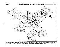
TO SET THE BLADE AT 0 ° AND 45 ° See Figures 47- 48. The angle settings of your saw have been set at the factory and, unless damaged in shipping, should not require setting during assembly. After extensive use, it may need to be checked. • Raise the blade and the blade guard. • If the blade is not perfectly vertical (O_),loosen the adjustment bolt and the bevel locking lever. • Place a combination square beside the blade on the left. Lock the angle by pushing the bevel locking lever and retighten the adjustment bolt. • Turn the bevel handJe until the bever indicator points to zero. If the bevel handle is turned as far as possible and doesn't indicate zero properly, you may need to adjust the bevel indicator. NOTE: It wirr be necessary to remove the bevel handle to adjust the bevel indicator. • fftha blade is not an exact 45_, loosen the adjustment bolt and the bevel locking laver. • Turn the bevel handle until the bottom of the blade has moved completely to the left side of the slot. Look the angle by pushing the bevel locking laver. • If the blade is net an exact 45 °, loosen the adjustment bolt and the bevel locking lever. • Adjust the bevel indicator to 45°. • Make a test cut. O° ADJUSTMENT BOLT BLADE COMBINATION SQUARE BEVELIND]CATOR BEVEL HANDLE BLADE BEVEL LOCKING LEVER Fig, 47 COMBINATION SQUARE BEVEL LOCKING LEVER BEVEL INDICATOR BEVEL HANDLE 45°ADJUSTMENT BOLT Fig. 48 34
-
 1
1 -
2
-
3
-
4
-
5
-
6
-
7
-
8
-
9
-
10
-
11
-
12
-
13
-
14
-
15
-
16
-
17
-
18
-
19
-
20
-
21
-
22
-
23
-
24
-
25
-
26
-
27
-
28
-
 29
29 -
 30
30 -
 31
31 -
 32
32 -
 33
33 -
 34
34 -
 35
35 -
 36
36 -
 37
37 -
 38
38 -
 39
39 -
40
-
41
-
42
-
43
-
44
-
45
-
46
-
47
-
48
 |
 |
