Craftsman 27675 Operation Manual - Page 21
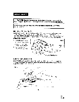
BRUSHREPLACEMENT, seeFig.11,11a,11band11c, Unplug, thesander.
 |
View all Craftsman 27675 manuals
Add to My Manuals
Save this manual to your list of manuals |
Page 21 highlights
BRUSHREPLACEMEN(sTeeFig.11,11a,11band 11c) 1. Unplugthesander. /_ WARNING: Failure to unplug the sander could result in accidental I starting causing possible serious personal injury. I 2. Remove (3) screws from top cover of sander and remove top cover (see Fig. 11). 3. Locate the (2) Carbon Brush / Brush Holder Assemblies (see Fig. 11a). They are connected to red wire lead terminals and are in position on each side of the armature. , Carefully lift these (2) assemblies (see Fig. 11a and 11b) out of their positions (NOTE: Remember how they are positioned so that you can put them back in position correctly.) 5. Check the ends of the carbon brushes (see Fig. 11b) for wear. If either brush has less than 1/4-in. length of carbon remaining, replace both. DO NOT REPLACE ONE S!DE WITHOUT REPLACING THE OTHER. 6. To replace assemblies, disconnect the red wire lead terminals from the assemblies (see Fig. 11c), attach new assemblies to the lead terminals and place the assemblies back into their original positions next to the armature. Make sure the curvature of the end of the brushes matches the curvature of the armature and that the brushes move freely in brush holder assemblies. Fig. 11 a 7. Reassemble the top cap with the (3) screws and do not overtighten. Fig. 11 Fig. 11b Red wire lead terminals Fig. 11c Carbon 21 27675 2/11/08
-
 1
1 -
2
-
3
-
4
-
5
-
6
-
7
-
8
-
9
-
10
-
11
-
12
-
13
-
14
-
15
-
 16
16 -
 17
17 -
 18
18 -
 19
19 -
 20
20 -
 21
21 -
 22
22 -
 23
23 -
 24
24 -
 25
25 -
 26
26 -
27
-
28
-
29
-
30
-
31
-
32
-
33
-
34
-
35
-
36
-
37
-
38
-
39
-
40
-
41
-
42
-
43
-
44
-
45
-
46
-
47
-
48
-
49
-
50
-
51
 |
 |
