Craftsman 28129 Operation Manual - Page 8
Forward
 |
UPC - 009281290001
View all Craftsman 28129 manuals
Add to My Manuals
Save this manual to your list of manuals |
Page 8 highlights
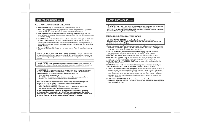
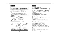
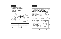
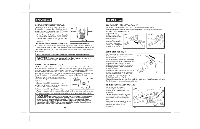
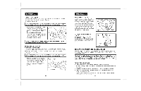
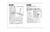
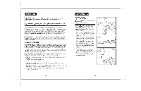
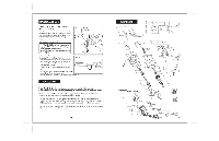
FORWAR/DREVERSE LEVER (Fig. 5) The direction of bit rotation, forward or reverse, is controlled by the lever above the trigger switch. Always have the trigger switch in the OFF position when operating the forward / reverse lever. 1. For the Forward Bit Rotation the lever should be to the left of the trigger switch (as you hold drill, pointing forward, looking down), pointing to the embossed arrow pointing forward towards the chuck. This forward position is used for Rotary drilling / driving and Hammer drilling. 2. To reverse Bit Rotation when in the Rotary drilling / driving mode only, move the lever to the right of the trigger, pointing to the embossed arrow pointing towards the rear of the drill. This reverse position is ONLY USED when rotary drilling / driving to back out screws and ammed bits. i NOTE: The hammer drilling function will not operate for reverse hammering. J Z_ CAUTION: To prevent gear damage, always allow the chuck to come to a i complete stop before changing the direction of rotation. J POWER LOCK=ON FEATURE (Fig. 6) The Power Lock-On button is for use only when the hammer drill is mounted in a drill press stand or otherwise held stationary. Do Not use the power lock-on feature when drilling or driving by hand, so you can instantly release the trigger switch and stop the drill if the bit binds in the hole or fastener. Be sure to release the power lock-on feature before disconnecting the plug from the power supply. Failure to do so will cause the hammer drill to start immediately the next time it is plugged in. Damage or injury could result. The power lock-on feature, is convenient for continuous drilling for extended periods of time. To lock-on: 1. Depress the variable speed trigger switch. 2. Push in and hold the lock-on button, located on the side of the drill's rear handle. Lock-On 3. Release the variable speed trigger switch. 4. Release the power lock-on button and the drill will continue running at maximun speed. 5. To release the power lock-on, depress and release the variable speed trigger switch. WARNING: Before connecting the drill to a power supply source, always check to be sure it is not in the power lock=on position by depressing and releasing the variable speed trigger switch. Failure to ensure that it is not locked=on could result in accidental starting of the drill, resulting in possible serious injury. DO NOT lock the variable speed trigger switch in applications where the drill may need to be suddenly stopped. 14 360 ° AUXILIARY HANDLE (Figs. 7 and 7a) The auxiliary handle clamps to the front of the gear case as shown (see Fig. 7). It can be rotated 360 ° to allow either right or left hand use, providing maximum balance and control in any operating position. To assemble the auxiliary handle onto Fig. 7 the drill, slide the clamp's assembly collar completely over and past the chuck onto the front of the drill's gear case (see Fig. 7a) and tighten by twisting the handle. DEPTH STOP ROD (Fig. 8) The Depth Stop Rod is used to control the depth of a hole when you are not through-drilling. The depth stop rod mounts into the clamp's assembly collar of the 360°auxiliary handle. To adjust the depth stop rod, forward or backwards, loosen the collar of the clamp assembly by twisting the auxiliary handle to loosen or tighten. To adjust the depth stop rod for drilling to a selected hole depth, move the rod so that the distance between the end of the rod and the end of the drill bit equals the desired hole depth (see Fig. 8). When drilling, stop when the end of the depth stop rod touches the surface you're drilling tn. The depth stop rod is marked in inches, 1 through 7. 1/2=iN. KEYED STEEL CHUCK (Fig. 9) The steel chuck is designed, constructed and machined for heavy-duty use, durability and long service life. Easily and securely install or remove accessory bits using the chuck key provided and the spindle lock on the drill. Apply a light coat of premium machine oil to the surface of the chuck face and jaws from time to time for rust resistance. 15 / /I
-
 1
1 -
2
-
 3
3 -
 4
4 -
 5
5 -
 6
6 -
 7
7 -
 8
8 -
 9
9 -
 10
10 -
 11
11 -
 12
12 -
 13
13 -
14
 |
 |
