Craftsman 28992 Operation Manual - Page 27
Check, Clutch
 |
View all Craftsman 28992 manuals
Add to My Manuals
Save this manual to your list of manuals |
Page 27 highlights
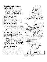
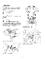
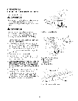
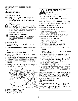
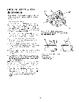
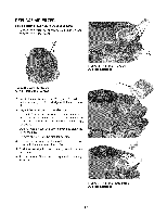
CHECK / ADJUST PTO CLUTCH WARNING To avoid serious injury, perform adjustments only with engine stopped, key removed and tractor on level ground. Service Interval: 200 Hours. The Power Take Off (PTO) clutch drives the mower blades. The PTO clutch is engaged and disengaged by the mower blade switch. Check the PTO clutch adjustment every 200 hours of operation. Also perform the following procedure if the clutch is slipping, will not engage, or if a new clutch has been installed. 1. Remove key from ignition switch and disconnect spark plug wires to prevent the possibility of accidental starting while the PTO is being adjusted. 2. Note the position of the 3 adjustment windows (A, Figure 28) in the side of the brake plate and the nylock adjustment nuts (B). 3. Insert a .012"-.015" (2,5-4 mm) feeler gauge (C) through each window, positioning the gauge between the rotor face and the armature face as shown in Figure 29. 4. Alternately tighten the adjustment nuts (B, Figure 29) until the rotor face and armature face just contacts the gauge. 5. Check the windows for an equal amount of tension when the gauge is inserted and removed, and make any necessary adjustments by tightening or loosening the adjustment nuts. NOTE: The actual air gap between the rotor and armature may vary even after performing the adjustment procedure. This is due to dimensional variations on component parts, and is an acceptable condition. 6. Check the mower blade stopping time. The mower blades and mower drive belt should come to a complete stop within five seconds after the electric PTO switch is turned off. If adjustment does not stop a mower braking problem, replace the electric PTO clutch. Figure 28. PTO Clutch Adjustment A. Adjustment Window (Qty. 3, one shown) B. Adjustment Nut (3) Figure 29. Adjust PTO Clutch A. Window B. Adjustment Nut C. Feeler Gauge 27
-
 1
1 -
2
-
3
-
4
-
5
-
6
-
7
-
8
-
9
-
10
-
11
-
12
-
13
-
14
-
15
-
16
-
17
-
18
-
19
-
20
-
21
-
 22
22 -
 23
23 -
 24
24 -
 25
25 -
 26
26 -
 27
27 -
 28
28 -
 29
29 -
 30
30 -
 31
31 -
 32
32 -
33
-
34
-
35
-
36
-
37
-
38
-
39
-
40
-
41
-
42
-
43
-
44
-
45
-
46
-
47
-
48
-
49
-
50
-
51
-
52
-
53
-
54
-
55
-
56
-
57
-
58
-
59
-
60
-
61
-
62
-
63
-
64
-
65
-
66
-
67
-
68
-
69
-
70
-
71
-
72
-
73
-
74
-
75
-
76
-
77
-
78
-
79
-
80
-
81
-
82
-
83
-
84
-
85
-
86
-
87
-
88
-
89
-
90
-
91
-
92
-
93
-
94
-
95
-
96
-
97
-
98
-
99
-
100
-
101
-
102
-
103
-
104
-
105
-
106
-
107
-
108
-
109
-
110
-
111
-
112
-
113
-
114
-
115
-
116
-
117
-
118
-
119
-
120
 |
 |
