Cub Cadet GTX 1054 Garden Tractor GTX 1054 Operator's Manual - Page 12
Controls and Features
 |
View all Cub Cadet GTX 1054 Garden Tractor manuals
Add to My Manuals
Save this manual to your list of manuals |
Page 12 highlights
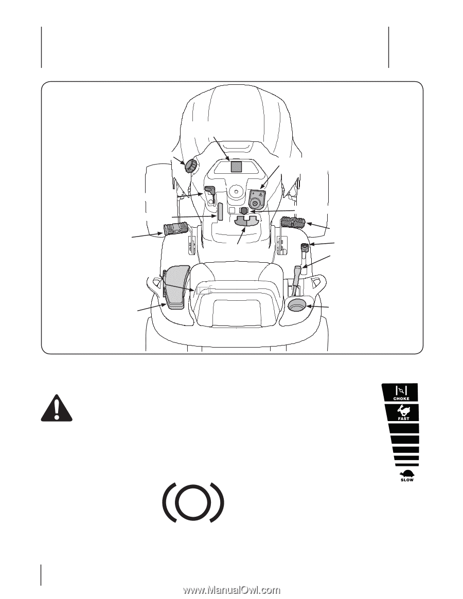
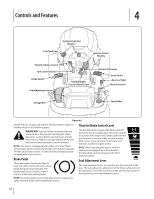
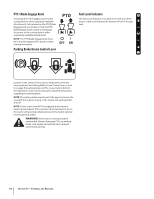
Controls and Features 4 Systems Indicator Monitor Fuel Tank Cap Ignition Switch Module Throttle/Choke Control Fuel Level Indicator Brake Pedal Seat Adjustment Lever Parking Brake/ Cruise Control Lever Electric PTO Knob Drive Pedal Reverse Pedal Deck Lift Lever Storage Bin Cup Holder Figure 4-1 Garden Tractor controls and features are illustrated in Figure 4-1 and described on the following pages. WARNING! Read and follow all safety rules and instructions in this manual, including the entire Operation section, before attempting to operate this machine. Failure to comply with all safety rules and instructions may result in personal injury. NOTE: Your tractor is equipped with either a Throttle/Choke Control Lever which controls the throttle and choke or separate Throttle and Choke controls. Use the controls and features that are applicable to your tractor. Brake Pedal The brake pedal is located on the left front side of the tractor above the drive pedal along the running board. The brake pedal can be used for sudden stops or setting the parking brake. NOTE: The brake pedal must be fully depressed to activate the safety interlock switch when starting the tractor. Throttle/Choke Control Lever The throttle/choke control is located on the left side of the tractor's dash panel. This lever controls the speed of the engine and, when pushed all the way forward, closes the choke for cold starting. When set in a given position, the throttle will maintain a uniform engine speed. NOTE: When operating the tractor with the cutting deck engaged, be certain that the throttle/choke control is always in the FAST (rabbit) position. Seat Adjustment Lever The seat adjustment lever is located below the front/left of the seat. The lever allows for adjustment of the fore to aft position of the operator's seat. Refer to the Assembly and Set-Up section of this manual for more detailed instructions. 12
-
 1
1 -
2
-
3
-
4
-
5
-
6
-
 7
7 -
 8
8 -
 9
9 -
 10
10 -
 11
11 -
 12
12 -
 13
13 -
 14
14 -
 15
15 -
 16
16 -
 17
17 -
18
-
19
-
20
-
21
-
22
-
23
-
24
-
25
-
26
-
27
-
28
-
29
-
30
-
31
-
32
-
33
-
34
-
35
-
36
 |
 |