Cub Cadet GTX 1054 Garden Tractor GTX 1054 Operator's Manual - Page 24
Deck Rear Roller Adjustment
 |
View all Cub Cadet GTX 1054 Garden Tractor manuals
Add to My Manuals
Save this manual to your list of manuals |
Page 24 highlights
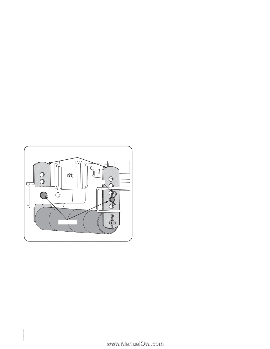
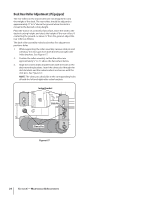
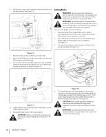
Deck Rear Roller Adjustment (If Equipped) The rear rollers on the mower deck are not designed to carry the weight of the deck. The rear rollers should be adjusted to approximately 1⁄4" to 1⁄2" above the ground when the deck is moved to the desired cutting height. Place the tractor on a smooth, flat surface, move the deck to the desired cutting height, and check the height of the rear rollers. If contacting the ground, or above 1⁄2" from the ground, adjust the rear rollers as follows: The deck roller assembly index bracket has five adjustment positions holes. 1. While supporting the roller assembly, remove click pin and withdraw the clevis pin from both the left and right roller index brackets. See Figure 6-7. 2. Position the roller assembly so that the rollers are approximately 1⁄4" to 1⁄2" above the flat surface below. 3. Align the nearest index bracket holes with the holes in the deck mounting brackets. Insert the clevis pins through the deck brackets and the index brackets and secure with the click pins. See Figure 6-7. NOTE: The clevis pins should be in the corresponding holes of both the left and right roller index brackets. Index Bracket Click Pin Clevis Pin Figure 6-7 24 Section 6 - Maintenance & Adjustments
-
 1
1 -
2
-
3
-
4
-
5
-
6
-
7
-
8
-
9
-
10
-
11
-
12
-
13
-
14
-
15
-
16
-
17
-
18
-
 19
19 -
 20
20 -
 21
21 -
 22
22 -
 23
23 -
 24
24 -
 25
25 -
 26
26 -
 27
27 -
 28
28 -
 29
29 -
30
-
31
-
32
-
33
-
34
-
35
-
36
 |
 |