Cub Cadet GTX 1054 Garden Tractor GTX 1054 Operator's Manual - Page 9
Assembly & Set-Up - tires
 |
View all Cub Cadet GTX 1054 Garden Tractor manuals
Add to My Manuals
Save this manual to your list of manuals |
Page 9 highlights
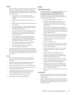
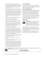
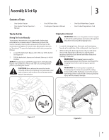
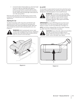
Assembly & Set-Up 3 Contents of Crate • One Garden Tractor • One Garden Tractor Operator's Manual • One Oil Drain Tube • One Engine Operator's Manual • One Deck Wash Hose Coupler • One Product Registration Card Tractor Set-Up Moving The Tractor Manually Your tractor's transmission is equipped with a hydrostatic relief valve for occasions when it is necessary to move the tractor manually. Opening this valve permits the fluid in the transmission to bypass its normal route, allowing the rear tires to "freewheel." To open the hydrostatic relief valve, proceed as follows: 1. Locate the hydrostatic bypass rod in the rear of the tractor. See Figure 3-1. 2. Pull the hydrostatic bypass rod outward, then up, to lock it in place. NOTE: The transmission will NOT engage when the hydrostatic bypass rod is pulled out. Return the rod to its normal position prior to operating the tractor. CAUTION: Never attempt to move the tractor manually without first opening the hydrostatic relief valve. Doing so will result in serious damage to the tractor's transmission. Shipping Brace Removal WARNING! Make sure the garden tractor's engine is off, set the parking brake and remove the ignition key before removing the shipping brace. 1. Locate the shipping brace, if present, and warning tag found on the right side of the cutting deck. See Figure 3-2. 2. While holding the discharge chute with your left hand, remove the shipping brace with your right hand by grasping it between your thumb and index finger and rotating it clockwise. WARNING! The shipping brace is used for packaging purposes only. Remove and discard the shipping brace before operating your garden tractor. WARNING! The mowing deck is capable of throwing objects. Failure to operate the riding mower without the discharge cover in the proper operating position could result in serious personal injury and/or property damage. Figure 3-1 Figure 3-2 9
-
 1
1 -
2
-
3
-
 4
4 -
 5
5 -
 6
6 -
 7
7 -
 8
8 -
 9
9 -
 10
10 -
 11
11 -
 12
12 -
 13
13 -
 14
14 -
15
-
16
-
17
-
18
-
19
-
20
-
21
-
22
-
23
-
24
-
25
-
26
-
27
-
28
-
29
-
30
-
31
-
32
-
33
-
34
-
35
-
36
 |
 |