Cub Cadet PRO Z 160S EFI Owners Manual - Page 10
Assembly & Set-Up - review
 |
View all Cub Cadet PRO Z 160S EFI manuals
Add to My Manuals
Save this manual to your list of manuals |
Page 10 highlights
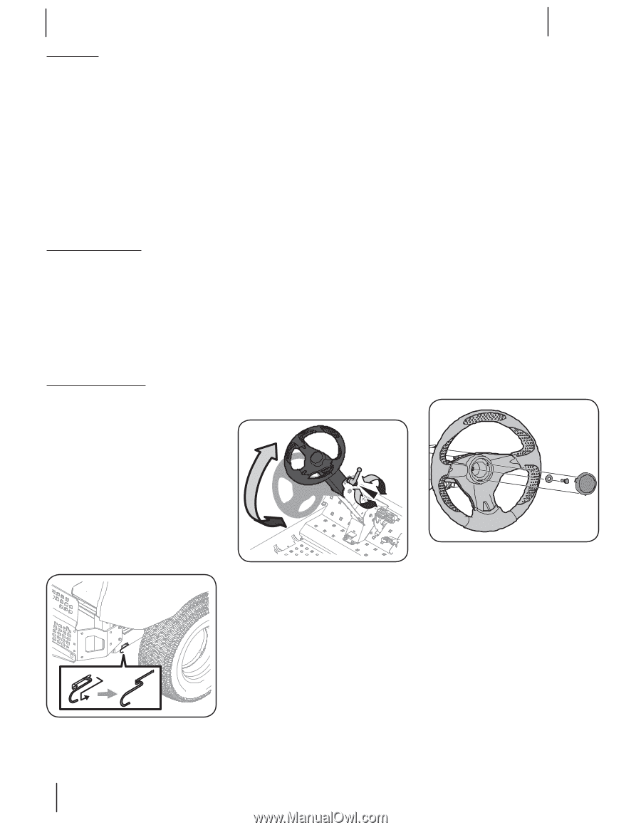
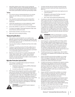
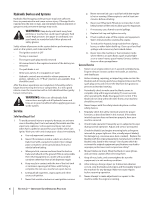
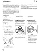
Assembly & Set-Up Thank You Thank you for purchasing this product. It was carefully engineered to provide excellent performance when properly operated and maintained. Please read this entire manual prior to operating the equipment. It instructs you how to safely and easily set up, operate and maintain your machine. Please be sure that you, and any other persons who will operate the machine, carefully follow the recommended safety practices at all times. Failure to do so could result in personal injury or property damage. All information in this manual is relative to the most recent product information available at the time. Review this manual frequently to familiarize yourself with the machine, its features and operation. Please be aware that this Operator's Manual may cover a range of product specifications for various models. Characteristics and features discussed and/or illustrated in this manual may not be applicable to all models. We reserve the right to change product specifications, designs and equipment without notice and without incurring obligation. 2 If applicable, the power testing information used to establish the power rating of the engine equipped on this machine can be found at www.opei.org or the engine manufacturer's web site. If you have any problems or questions concerning the machine, phone your local authorized service dealer or contact us directly. We want to ensure your complete satisfaction at all times. Throughout this manual, all references to right and left side of the machine are observed from the operating position. Contents of Carton • Tractor (1) • Engine Operator's Manual (1) • Steering Wheel Assembly (1) • Operator's Manual (1) NOTE: This Operator's Manual covers several models. Features may vary by model. Not all features in this manual are applicable to all models and the model depicted may differ from yours. NOTE: All references in this manual to the left or right side and front or back of the tractor are from the operating position only. Exceptions, if any, will be specified. Tractor Preparation Lubrication & Grease Points Before operating the tractor, refer to the Service section of this manual to check the Lubrication & Grease Points. Grease and lubricate if necessary. Steering Wheel Column (If necessary) The steering wheel column is tilted all the way back for shipping purposes. To tilt the column forward, rotate the steering column adjustment lever (a) counter-clockwise, place the column in the desired position and then rotate the steering column adjustment lever (a) lever clockwise to secure the column in place. See Figure 2-2. Steering Wheel (If necessary) 1. Remove the hardware for attaching the steering wheel (a) from beneath the steering wheel cover (b). Carefully pry off the steering wheel cover (b)to remove the hardware. See Figure 2-3. Manually Moving the Tractor 1. Engage the transmission bypass rods, one on each side of the tractor, to move the tractor manually without starting it. The transmission bypass rods are located on the rear of the tractor, just inside each rear wheel. Disengage the parking brake and engage the bypass rods by pulling each one back (a) and hooking it into the slot (b) to lock it into place. See Figure 2-1. a b (a) Figure 2-2 NOTE: Be sure that the steering column adjustment lever is tight to prevent the column from moving when operating the machine. (c) (d) (b) (a) Figure 2-3 2. With the wheels of the machine pointing straight forward, place the steering wheel (a) over the steering shaft.See Figure 2-3. 3. Place the belleville washer (c) with the cupped side facing inward over the steering wheel (a) and secure with the hex lock screw (d). See Figure 2-3. 4. Place the steering wheel cover (b) over the center of the steering wheel (a) and push downward until it "clicks" into place. Figure 2-1 2. Disengage the bypass rods by reversing steps a & b after moving the tractor. See Figure 2-1. 10
-
 1
1 -
2
-
3
-
4
-
 5
5 -
 6
6 -
 7
7 -
 8
8 -
 9
9 -
 10
10 -
 11
11 -
 12
12 -
 13
13 -
 14
14 -
 15
15 -
16
-
17
-
18
-
19
-
20
-
21
-
22
-
23
-
24
-
25
-
26
-
27
-
28
 |
 |