Cub Cadet PRO Z 160S EFI Owners Manual - Page 14
Seat Adjustment Lever
 |
View all Cub Cadet PRO Z 160S EFI manuals
Add to My Manuals
Save this manual to your list of manuals |
Page 14 highlights
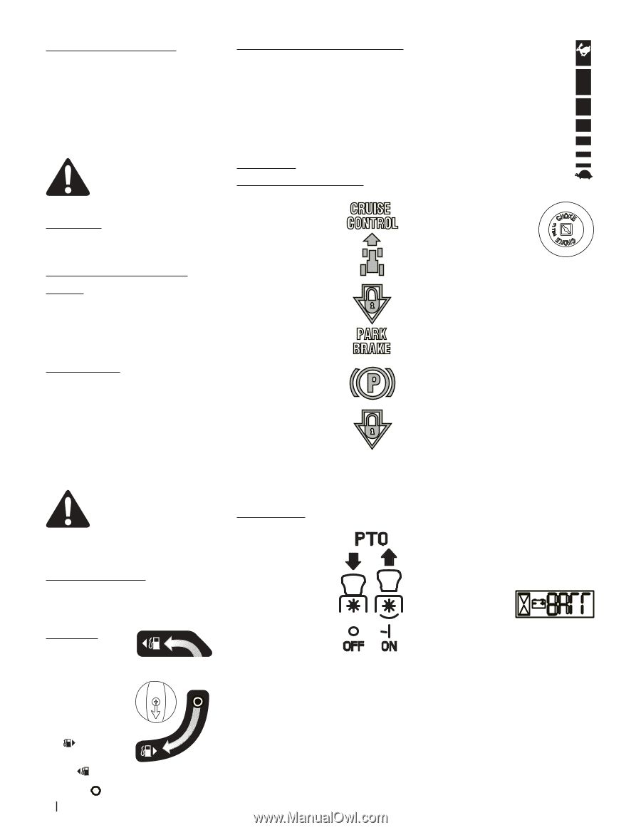
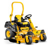
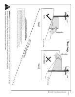
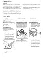
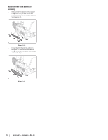
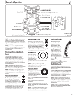
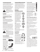
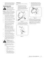
Transmission Bypass Rods The transmission bypass rods (one for each the RH and LH transmission) are located on the rear of the tractor, just inside each rear wheel. When engaged and the parking brake disengaged, the two rods open a bypass within the hydrostatic transmissions, which allows the tractor to be pushed short distances by hand. Refer to the Assembly & Set-Up section for instructions on using the bypass feature. CAUTION: Never tow your tractor. Towing the tractor with the rear wheels on the ground may cause severe damage to the transmissions. Cup Holder The cup holder is located to the left of the operator's seat on the LH console. Seat Adjustment Lever (Not Shown) The seat adjustment lever is located below the front/right of the seat. The lever allows for adjustment forward or backward of the operator's seat. Refer to the Assembly & Set-Up section for instructions on adjusting the seat position. Fuel Tank Caps The fuel tank caps are located near the middle of the RH and LH console. Turn the fill cap to remove. The fuel cap is tethered to the tractor to prevent its loss. Do not attempt to remove the cap from the tractor. Fill tank to the bottom of the filler neck, allowing some space in the tank for fuel expansion. Do not overfill the tank. Turn clockwise until it clicks to tighten. Always re-install the fuel cap tightly onto the fuel tank after removing. WARNING! Never fill the fuel tank when the engine is running. If the engine is hot from recently running, allow to cool for several minutes before refueling. Highly flammable gasoline could splash onto the engine and cause a fire. Fuel Level Windows The fuel level windows are located on the outside of the LH and RH consoles and shows the level of fuel in the gas tank. Fuel Valve The fuel valve is located on the inner side of the RH console. The valve switches the fuel flow from the right and left tank and also can shut off fuel flow to the engine. Rotate the valve to the rear to open the flow from the right fuel tank . Rotate the valve to the front to open the flow from the left tank . To shut off fuel from both tanks rotate the valve towards the right of the tractor and the OFF position. 14 Section 3 - Controls & Operation Transmission Oil Expansion Reservoir The transmission oil expansion reservoir is connected by hoses to the RH and LH transmission assemblies, and is located behind the seat box. The function of the reservoir is to hold the natural expansion of transmission oil that occurs as the transmission warms up during operation. See the Service section for more information on the transmission oil expansion reservoir. Park Brake/ Cruise Control Lock Pedal The park brake/cruise control CRUISE lock pedal is located at the CONTROL base of the steering column. It is used to engage the park brake when the tractor is at rest. Engaging the lever while the tractor is in motion allows the tractor to remain at a constant ground speed without applying pressure to the forward drive pedal. Refer to the Operation section of this manual for detailed instructions regarding the parking brake as well as the cruise control PARK BRAKE feature. NOTE: Cruise control can NOT be engaged at the tractor's fastest ground speed. If the operator should attempt to do so, the tractor will automatically decelerate to the fastest optimal mowing ground speed NOTE: The park brake must be set if the operator leaves the seat with the engine running or the engine will automatically shut off. Control Panel PTO Switch (a) The PTO (Power Take-Off) switch is located on the RH console to the left of the hour meter/indicator panel. The PTO switch operates the electric PTO clutch mounted on the bottom of the engine crankshaft and engages the mower blades and engages the mower blades. Pull the switch knob upward to engage the PTO clutch, or push the knob downward to disengage the clutch. The PTO switch must be in the "disengaged" position when starting the engine. Throttle Control (b) The throttle control is located on the RH FAST console. When set in a given position, a uniform engine speed will be maintained. Push the throttle control handle forward to increase the engine speed. The tractor is designed to operate with the throttle control in the fast position (full throttle) when the tractor is being driven and the mower deck is engaged. Pull the throttle control handle rearward to decrease the engine speed Choke Control (If Equipped) (c) SLOW The choke control is located on the RH console. The choke control determines the position of the engine choke. Pull the knob out to choke the engine; push the knob in to open the choke. LCD Service Minder & Hour Meter (d) When the ignition key is rotated out of the STOP position but not into the START position, the LCD Service Minder and Hour Meter will briefly display the battery voltage, followed by the tractor's accumulated hours. NOTE: Hours of tractor operation are recorded any time the ignition key is rotated out of the STOP position, regardless of whether the engine is started. The LCD Service Minder will remind the operator of maintenance intervals for changing the engine oil, air filter service, low engine and low battery warnings. Change Oil The LCD will display the letters "CHG", followed by the letters "OIL", followed by the letters "SOON", then finally followed by the meter's accumulated time. "CHG/OIL/SOON/TIME" will alternate on the display for 7 minutes after the meter reaches 50 hours. This oil service minder interval will occur every 50 hours. Before the interval expires, change the engine oil as instructed in the Maintenance section of this Operator's Manual. Low Battery At startup, the battery voltage is briefly displayed then changes to accumulated hours. The letters "LO" will display followed by the letters "BATT" and then followed by the meter's accumulated time. "LO/BATT/TIME" is displayed on the LCD when the voltage drops below 11.5 volts. When this occurs, the battery is in need of a charge or the engine's charging system is not generating sufficient amperage. Charge the battery as instructed in the Service section of this manual or have the charging system checked by your local service dealer.
-
 1
1 -
2
-
3
-
4
-
5
-
6
-
7
-
8
-
 9
9 -
 10
10 -
 11
11 -
 12
12 -
 13
13 -
 14
14 -
 15
15 -
 16
16 -
 17
17 -
 18
18 -
 19
19 -
20
-
21
-
22
-
23
-
24
-
25
-
26
-
27
-
28
 |
 |