Cub Cadet Z-Force S Commercial 60 Z-Force S Commercial 48 Operator's Manual - Page 22
Adjustments
 |
View all Cub Cadet Z-Force S Commercial 60 manuals
Add to My Manuals
Save this manual to your list of manuals |
Page 22 highlights
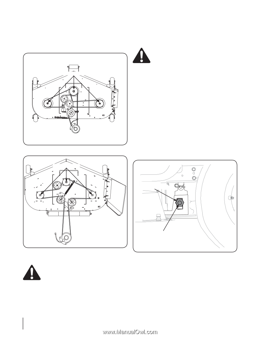
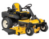
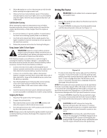
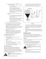
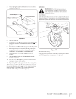
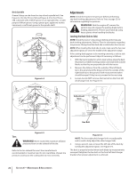
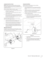
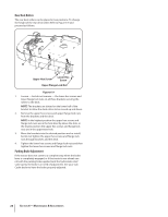
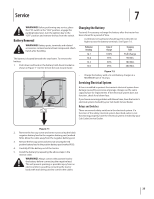
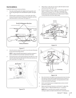
Deck Spindle Grease fittings can be found on top of each spindle bolt. See Figure 6-4 for the Z-Force S60 and Figure 6-5 for the Z-Force S48. Lubricate with 251H EP grease or an equivalent No. 2 multipurpose lithium grease. Using a grease gun, apply two strokes (minimum) or sufficient grease to the spindle shaft. Grease Fittings Figure 6-4 Adjustments NOTE: Check the tractor's tire pressure before performing any deck leveling adjustments. Refer to Tires on page 22 for information regarding tire pressure. WARNING! Shut the engine off, remove the ignition key and engage the parking brake before making adjustments. Protect your hands by using heavy gloves when handling the blades. Leveling the Deck (Side to Side) NOTE: Check the tractor's tire pressure before performing any deck leveling adjustments. Refer to Tires for information regarding tire pressure. Always level the deck side to side before front to rear. NOTE: When leveling the deck side-to-side, make sure the two rear adjustment gears are set in the middle of the adjustment range. If the cutting deck appears to be mowing unevenly, a side to side adjustment can be performed. Adjust if necessary as follows: 1. With the tractor parked on a firm, level surface, place the deck lift pedal in a middle mowing position and rotate both outside blades so that they are perpendicular with the tractor. 2. Measure the distance from the outside of the left blade tip to the ground and the distance from the outside of the right blade tip to the ground. Both measurements taken should be equal. If they're not, proceed to the next step. 3. Loosen, but do NOT remove, the hex bolt on the front left deck hanger link. See Figure 6-6. Grease Fittings Adjustment Gear Hex Bolt Tires Figure 6-5 WARNING! Never exceed the maximum inflation pressure shown on the sidewall of the tire. Refer to the tire sidewall for exact tire manufacturer's recommended or maximum psi. Do not overinflate. Uneven tire pressure could cause the cutting deck to mow unevenly. Figure 6-6 NOTE: The front right deck hanger link is not adjustable and is used to help adjust the other hanger links. 4. Using a wrench, raise or lower the left side of the deck by turning the adjustment gears. See Figure 6-6. The deck is properly leveled when both blade tip measurements are equal. Retighten the hex bolt on the front left deck hanger bracket when proper adjustment is achieved. 22 Section 6- Maintenance & Adjustments
-
 1
1 -
2
-
3
-
4
-
5
-
6
-
7
-
8
-
9
-
10
-
11
-
12
-
13
-
14
-
15
-
16
-
 17
17 -
 18
18 -
 19
19 -
 20
20 -
 21
21 -
 22
22 -
 23
23 -
 24
24 -
 25
25 -
 26
26 -
 27
27 -
28
-
29
-
30
-
31
-
32
-
33
-
34
-
35
-
36
 |
 |