Cub Cadet Z-Force S Commercial 60 Z-Force S Commercial 48 Operator's Manual - Page 27
Deck Installation
 |
View all Cub Cadet Z-Force S Commercial 60 manuals
Add to My Manuals
Save this manual to your list of manuals |
Page 27 highlights
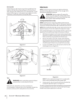
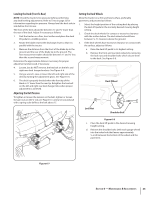
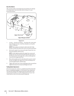
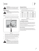
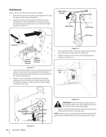
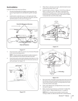
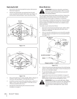
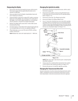
Deck Installation Install the deck on the tractor as follows: 1. Place the deck lift pedal in the highest mowing position and secure it by placing the lock rod behind the pedal. See Figure 7-3. 2. Slide the deck under the tractor on the right side of the tractor lining up the deck lift adjustment brackets and the deck lift brackets on the deck. See Figure 7-7. 5. After all four cotter pins are secure, slide the deck forward and hook the deck to the U-rod. 6. Route the belt as shown in Figure 7-9 for Z-Force S60 and Figure 7-10 for the Z-Force S48. After routing the belt around the PTO pulley, use a 1⁄2" drive in the idler pulley bracket and turn towards the front of the tractor to finish routing the belt around the idler pulley. Deck Lift Adjustment Brackets Deck Spindles Deck Belt Idler Pulley PTO Pulley PTO Belt Deck Lift Brackets Figure 7-7 3. Once the deck is under the tractor, move the deck lift pedal to the lowest mowing position. NOTE: To line the brackets up properly, it may be necessary to place a small block of wood under each side of the deck. 4. Once the brackets are properly aligned, slide the pin on the deck lift adjustment bracket into the lift bracket and secure with cotter pins. See Figure 7-8. Bracket Pin Cotter Pin Figure 7-9 Deck Spindles Idler Pulley PTO Pulley Figure 7-8 Figure 7-10 7. Place the deck in the highest mowing position by removing the click pin and push the pedal forward and rock back to lock into the transport position, locking behind the notch on the front of the index plate. 8. Refer to the Maintenance & Adjustments section to level the deck if required. 9. Make sure the proper tension is on the belt. To adjust the tension, refer to "Adjusting Belt Tension" on page 23. NOTE: Before using the tractor double-check the belt routing to make sure that the belt has been routed properly. Section 7 - Service 27
-
 1
1 -
2
-
3
-
4
-
5
-
6
-
7
-
8
-
9
-
10
-
11
-
12
-
13
-
14
-
15
-
16
-
17
-
18
-
19
-
20
-
21
-
 22
22 -
 23
23 -
 24
24 -
 25
25 -
 26
26 -
 27
27 -
 28
28 -
 29
29 -
 30
30 -
 31
31 -
 32
32 -
33
-
34
-
35
-
36
 |
 |
