D-Link DG-104SH Product Manual - Page 6
Getting Started
 |
View all D-Link DG-104SH manuals
Add to My Manuals
Save this manual to your list of manuals |
Page 6 highlights
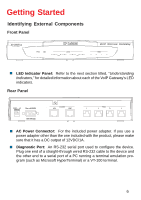
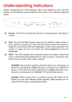
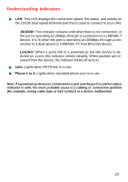
Getting Started Identifying External Components Front Panel DG-104SH „ LED Indicator Panel: Refer to the next section titled, "Understanding Indicators," for detailed information about each of the VoIP Gateway's LED indicators. Rear Panel „ AC Power Connector: For the included power adapter. If you use a power adapter other than the one included with the product, please make sure that it has a DC output of 12VDC/1A. „ Diagnostic Port: An RS-232 serial port used to configure the device. Plug one end of a straight-through wired RS-232 cable to the device and the other end to a serial port of a PC running a terminal emulation program (such as Microsoft HyperTerminal) or a VT-100 terminal. 6
-
 1
1 -
 2
2 -
 3
3 -
 4
4 -
 5
5 -
 6
6 -
 7
7 -
 8
8 -
 9
9 -
 10
10 -
 11
11 -
 12
12 -
13
-
14
-
15
-
16
-
17
-
18
-
19
-
20
-
21
-
22
-
23
-
24
-
25
-
26
-
27
-
28
-
29
-
30
-
31
-
32
-
33
-
34
-
35
-
36
-
37
-
38
-
39
-
40
-
41
-
42
-
43
-
44
-
45
-
46
-
47
-
48
-
49
-
50
-
51
-
52
-
53
-
54
-
55
-
56
-
57
-
58
-
59
-
60
-
61
-
62
-
63
-
64
-
65
-
66
-
67
-
68
-
69
-
70
-
71
-
72
-
73
-
74
-
75
-
76
-
77
-
78
-
79
-
80
-
81
-
82
-
83
 |
 |
6
Getting Started
Identifying External Components
LED Indicator Panel:
Refer to the next section titled, “
Understanding
Indicators
,” for detailed information about each of the VoIP Gateway’s LED
indicators.
Front Panel
Rear Panel
AC Power Connector:
For the included power adapter. If you use a
power adapter other than the one included with the product, please make
sure that it has a DC output of 12VDC/1A.
Diagnostic Port:
An RS-232 serial port used to configure the device.
Plug one end of a straight-through wired RS-232 cable to the device and
the other end to a serial port of a PC running a terminal emulation pro-
gram (such as Microsoft HyperTerminal) or a VT-100 terminal.
DG-104SH