D-Link DGS-1100-08PV2 User Manual 1.00 WW - Page 6
Rear Panel, DGS-1100-05PDV2, Front Panel, Link/Act/Speed LED Ports 1-5
 |
View all D-Link DGS-1100-08PV2 manuals
Add to My Manuals
Save this manual to your list of manuals |
Page 6 highlights
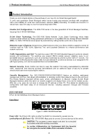
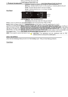
1 Product Introduction Rear Panel D-Link Smart Managed Switch User Manual Figure 1.2 - DGS-1100-05V2 Rear Panel Power: Input for a 5V/1A AC adapter. Reset: Press the Reset button for 1 to 5 seconds to reboot the Switch. Press the Reset button for 6 to10 seconds to reset the Switch back to the default settings. The LED will light up solid amber for 2 seconds. When pressing the Reset button for longer than 10 seconds, the device will enter loader mode and the LED will light up solid green for 2 seconds. If the device cannot reboot, it will automatically enter loader mode. Alternatively, you can press Reset to power up the device and enter loader mode. Kensington Lock: This is used to attach a physical Kensington security lock. GND: This is used to connect the Switch to ground. DGS-1100-05PDV2 2-Port 10/100/1000Mbps PoE and 3-Port 10/100/1000Mbps with 1 PD port Smart Managed Switch. Front Panel Figure 1.3 - DGS-1100-05PDV2 Front Panel Power LED: The Power LED lights up when the Switch is connected to a power source. If the Power LED is Blinking, PoE Pass Through is Off. Link/Act/Speed LED (Ports 1-5): Flashing: Indicates a network link through the corresponding port. Blinking: Indicates that the Switch is either sending or receiving data to the port. Green: Indicates that the port is running at 1000M. Amber: Indicates that the port is running at 10/100M. Light off: No link. PoE PSE LED (Port 1-2): Solid Green: PD device insert and power feeding. Solid Amber: PD device insert but failure occurs. Light off: No PD device insert. PoE PD (Port 5): Solid Green: Receiving power from PSE per 802.3at. Solid Amber: Receiving power from PSE per PSE. Light off: No link. Reset: Press the Reset button for 1 to 5 seconds to reboot the Switch. Press the Reset button for 6 to10 seconds to reset the Switch back to the default settings. The LED will light up solid amber for 2 seconds. When pressing the Reset button for longer than 10 seconds, the device will enter loader mode and the LED will light up solid green for 2 seconds. If the device cannot reboot, it will automatically enter loader mode. Alternatively, you can press Reset to power up the device and enter loader mode. CAUTION: This equipment can be connected only to PoE networks without routing to the outside plant. 3
-
 1
1 -
 2
2 -
 3
3 -
 4
4 -
 5
5 -
 6
6 -
 7
7 -
 8
8 -
 9
9 -
 10
10 -
 11
11 -
 12
12 -
13
-
14
-
15
-
16
-
17
-
18
-
19
-
20
-
21
-
22
-
23
-
24
-
25
-
26
-
27
-
28
-
29
-
30
-
31
-
32
-
33
-
34
-
35
-
36
-
37
-
38
-
39
-
40
-
41
-
42
-
43
-
44
-
45
-
46
-
47
-
48
-
49
-
50
-
51
-
52
-
53
-
54
-
55
-
56
 |
 |
