D-Link DGS-1100-08PV2 User Manual 1.00 WW - Page 9
Rear Panel, LED Indicators
 |
View all D-Link DGS-1100-08PV2 manuals
Add to My Manuals
Save this manual to your list of manuals |
Page 9 highlights
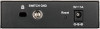
1 Product Introduction D-Link Smart Managed Switch User Manual Rear Panel CAUTION: The equipment power supply cord shall be connected to a socket-outlet with earthing connection. Le cordon d'alimentation de l'équipement doit être branché sur une prise de courant dotée d'une connexion à la terre. Figure 1.8 - DGS-1100-08PV2 Rear Panel Power: Input for a 54V/1.574A AC adapter. Kensington Lock: This is used to attach a physical Kensington security lock. GND: This is used to connect the Switch to ground. NOTE: The power budget is 64 Watts for DGS-1100-08P. LED Indicators The Switches feature LED indicators for Power and Link/Act for each port. The following shows the LED indicators for the DGS-1100-05V2/05PDV2/08V2/08PV2 switches along with an explanation of each indicator. Location Per Device LED Per 10/100/1000 Mbps Port Figure 1.9 -LED Indicators on DGS-1100 series Indicator LED Color Status Description Solid Light The device is powered on. Power Green Blinking PoE Pass Through Off (DGS-110005PDV2 only) Light off The device is powered off. PoE Max. (Only DGS-1100- Red 08PV2) Solid Light Blinking When the power output to PDs is over 57W. No additional PDs can be powered for safety consideration. If the user unplugged certain PDs and made the PoE power budget left over 7W, the PoE MAX LED will blink 5 seconds. Light off When the power budget is using less the 57W. Link/Act/Speed Green/Amber Solid Green Blinking Indicates there is a 1000 Mbps connection on this port. Indicates data is being processed on Green this port at 1000 Mbps. 6
-
 1
1 -
2
-
3
-
 4
4 -
 5
5 -
 6
6 -
 7
7 -
 8
8 -
 9
9 -
 10
10 -
 11
11 -
 12
12 -
 13
13 -
 14
14 -
15
-
16
-
17
-
18
-
19
-
20
-
21
-
22
-
23
-
24
-
25
-
26
-
27
-
28
-
29
-
30
-
31
-
32
-
33
-
34
-
35
-
36
-
37
-
38
-
39
-
40
-
41
-
42
-
43
-
44
-
45
-
46
-
47
-
48
-
49
-
50
-
51
-
52
-
53
-
54
-
55
-
56
 |
 |
