D-Link DGS-1520-28MP Product Manual 1 - Page 13
Rear Panel LED Indicators, DGS-1520-52MP, Redundant Power Supply, per device, Link/Act
 |
View all D-Link DGS-1520-28MP manuals
Add to My Manuals
Save this manual to your list of manuals |
Page 13 highlights
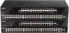
Port DGS-1520 Series Gigabit Ethernet Smart Managed Switch Hardware Installation Guide Description The MGMT port can also be used to supply the Switch with 90W DC power using Power over HDBaseT. This can be used as the main power source or as the secondary power source to the Switch. Figure 2-12 DGS-1520-52MP Rear Panel This following table lists the front panel components unique to the DGS-1520-52MP: Port Description Redundant Power Supply The RPS port can be used to connect an optional external load-sharing RPS to the Switch. When the internal power fails, the external RPS will immediately supply power to the Switch automatically. Rear Panel LED Indicators The rear panel LED indicators provide valuable information in a variety of ways like their color, blinking times, and location. Figure 2-13 DGS-1520-28/52 Rear Panel LED Indicators The rear panel LED indicators (per device) are described in the following table: LED Color Status Description Link/Act Green On (Solid) Active connection at 1 Gbps through the MGMT port On (Blinking) Data transmitted and received through the MGMT port Amber On (Solid) Active connection at 10/100 Mbps through the MGMT port On (Blinking) Data transmitted and received through the MGMT port Off Off Inactive connection or no link present PD Green On (Solid) Receiving DC power from PoH PSE connected to the MGMT port Amber On (Solid) Normal MGMT connection active (no PoH supplied). When a PSE is connected, this light indicates that a power supply failure has occurred. Off Off No PoH PSE or MGMT connection is present 8
-
 1
1 -
2
-
3
-
4
-
5
-
6
-
7
-
 8
8 -
 9
9 -
 10
10 -
 11
11 -
 12
12 -
 13
13 -
 14
14 -
 15
15 -
 16
16 -
 17
17 -
 18
18 -
19
-
20
-
21
-
22
-
23
-
24
-
25
-
26
-
27
-
28
-
29
-
30
-
31
-
32
-
33
-
34
-
35
-
36
-
37
-
38
-
39
-
40
-
41
-
42
-
43
-
44
-
45
-
46
-
47
-
48
-
49
-
50
-
51
-
52
-
53
-
54
-
55
-
56
-
57
-
58
-
59
-
60
-
61
-
62
 |
 |
