D-Link DGS-1520-28MP Product Manual 1 - Page 28
Switch to Switch, Duplex Chain Stacking Topology Odd, 4-port
 |
View all D-Link DGS-1520-28MP manuals
Add to My Manuals
Save this manual to your list of manuals |
Page 28 highlights
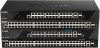
DGS-1520 Series Gigabit Ethernet Smart Managed Switch Hardware Installation Guide In the following diagram, an odd number of switches (for example 3 switches) are stacked in the duplex chain topology using the 4-port stacking configuration. Figure 4-5 Duplex Chain Stacking Topology (Odd, 4-port) In the following diagram, an odd number of switches (for example 3 switches) are stacked in the duplex ring topology using the 4-port stacking configuration. The topology is not supported on switches in this series. Figure 4-6 Duplex Ring Stacking Topology (Odd, 4-port) Switch to Switch The Switch can be used to connect to any other switch or hub in the network. This network topology is used when the Switch does not have enough ports to cater for all the end nodes in the network. There is a great deal of flexibility on how connections are made using the appropriate cabling. • Connect a 10BASE-T or 100BASE-TX switch port to the Switch using a Category 3/4/5 UTP/STP cable. • Connect a 1000BASE-T switch port to the Switch via a Category 5e UTP/STP cable. • Connect a 2.5GBASE-T switch port to the Switch via a Category 5e/6 UTP/STP cable. • Connect a 10GBASE-T switch port to the Switch via a Category 6a UTP/STP cable. • Connect a fiber uplink switch port to the Switch's SFP+ port via a fiber optical cable. 23
-
 1
1 -
2
-
3
-
4
-
5
-
6
-
7
-
8
-
9
-
10
-
11
-
12
-
13
-
14
-
15
-
16
-
17
-
18
-
19
-
20
-
21
-
22
-
 23
23 -
 24
24 -
 25
25 -
 26
26 -
 27
27 -
 28
28 -
 29
29 -
 30
30 -
 31
31 -
 32
32 -
 33
33 -
34
-
35
-
36
-
37
-
38
-
39
-
40
-
41
-
42
-
43
-
44
-
45
-
46
-
47
-
48
-
49
-
50
-
51
-
52
-
53
-
54
-
55
-
56
-
57
-
58
-
59
-
60
-
61
-
62
 |
 |
