D-Link DGS-3130 Quick Install Guide - Page 37
DPS-700, Install the DPS-500A in the DPS-800
 |
View all D-Link DGS-3130 manuals
Add to My Manuals
Save this manual to your list of manuals |
Page 37 highlights
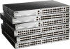
DGS-3130 Series Layer 3 Stackable Managed Switch Hardware Installation Guide Figure 3-11 Install the DPS-500A in the DPS-800 The DPS-800 can be mounted into a standard 19" rack, as shown below. Figure 3-12 Install the DPS-800 in an Equipment Rack DPS-700 The DPS-700 is connected to the Master Switch using a 22-pin DC power cable. A standard, three-pronged AC power cable connects the redundant power supply to the main power source. 37
-
 1
1 -
2
-
3
-
4
-
5
-
6
-
7
-
8
-
9
-
10
-
11
-
12
-
13
-
14
-
15
-
16
-
17
-
18
-
19
-
20
-
21
-
22
-
23
-
24
-
25
-
26
-
27
-
28
-
29
-
30
-
31
-
 32
32 -
 33
33 -
 34
34 -
 35
35 -
 36
36 -
 37
37 -
 38
38 -
 39
39 -
 40
40 -
 41
41 -
 42
42 -
43
-
44
-
45
-
46
-
47
-
48
-
49
-
50
-
51
-
52
-
53
-
54
-
55
-
56
-
57
-
58
-
59
-
60
-
61
-
62
-
63
-
64
-
65
-
66
-
67
-
68
-
69
-
70
-
71
-
72
-
73
-
74
-
75
-
76
 |
 |

DGS-3130 Series Layer 3 Stackable Managed Switch Hardware Installation Guide
37
Figure 3–11 Install the DPS-500A in the DPS-800
The DPS-800 can be mounted into a standard 19" rack, as shown below.
Figure 3–12 Install the DPS-800 in an Equipment Rack
DPS-700
The DPS-700 is connected to the Master Switch using a 22-pin DC power cable. A standard, three-pronged AC power
cable connects the redundant power supply to the main power source.