D-Link DGS-3427 Product Manual - Page 15
xStack, DGS-3400 Series Layer 2 Gigabit Ethernet Managed Switch, Web TCP Port - d link manual
 |
UPC - 790069283161
View all D-Link DGS-3427 manuals
Add to My Manuals
Save this manual to your list of manuals |
Page 15 highlights
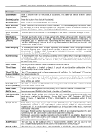
xStack® DGS-3400 Series Layer 2 Gigabit Ethernet Managed Switch Parameter Description System Name Enter a system name for the Switch, if so desired. This name will identify it in the Switch network. System Location Enter the location of the Switch, if so desired. System Contact Enter a contact name for the Switch, if so desired. Serial Port Auto Logout Time Select the logout time used for the console interface. This automatically logs the user out after an idle period of time, as defined. Choose from the following options: 2 Minutes, 5 Minutes, 10 Minutes, 15 Minutes or Never. The default setting is 10 minutes. Serial Port Baud This field specifies the baud rate for the serial port on the Switch. The default setting is 115200. Rate MAC Address Aging Time (101000000) This field specifies the length of time a learned MAC Address will remain in the forwarding table without being accessed (that is, how long a learned MAC Address is allowed to remain idle). To change this, type in a different value representing the MAC address age-out time in seconds. The MAC Address Aging Time can be set to any value between 10 and 1,000,000 seconds. The default setting is 300 seconds. IGMP Snooping To enable system-wide IGMP Snooping capability, select Enabled. IGMP snooping is Disabled by default. Enabling IGMP snooping allows the user to specify use of a multicast router only (see below). To configure IGMP Snooping for individual VLANs, use the IGMP Snooping window under the IGMP Snooping folder. MLD Snooping To enable system-wide MLD Snooping capability, select Enabled. MLD snooping is Disabled by default. Enabling MLD snooping allows you to specify use of a multicast router only (see below). To configure MLD Snooping for individual VLANs, use the MLD Snooping window under the MLD Snooping folder. GVRP Status Use this pull-down menu to enable or disable GVRP on the Switch. Telnet Status Telnet configuration is Enabled by default. If you do not want to allow configuration of the system through Telnet choose Disabled. Telnet TCP Port The TCP port number used for Telnet management of the Switch. The "well-known" TCP port for Number (1-65535) the Telnet protocol is 23. Web Status Web-based management is Enabled by default. If you choose to disable this by selecting Disabled, you will lose the ability to configure the system through the Web interface as soon as these settings are applied. Web TCP Port The TCP port number used for Web-based management of the Switch. The "well-known" TCP Number (1-65535) port for the Telnet protocol is 80. SNMP Status Simple Network Management Protocol (SNMP) of the Switch is Enabled or Disabled here. RMON Status Remote monitoring (RMON) of the Switch is Enabled or Disabled here. Link Aggregation Algorithm The algorithm that the Switch uses to balance the load across the ports that make up the port trunk group is defined by this definition. Choose MAC Source, MAC Destination, MAC Src & Dest, IP Source, IP Destination or IP Src & Dest (See the Link Aggregation section of this manual). Switch 802.1X MAC Address may enable by port or the Switch's 802.1X function; the default is Disabled. This field must be enabled to view and configure certain windows for 802.1X. More information regarding 802.1X, its functions and implementation can be found later in this section, under the Port Access Entity folder. Port-based 802.1X specifies that ports configured for 802.1X are initialized based on the port number only and are subject to any authorization parameters configured. MAC-based Authorization specifies that ports configured for 802.1X are initialized based on the port number and the MAC address of the computer being authorized and are then subject to any authorization parameters configured. Auth Protocol The user may use the pull-down menu to choose between RADIUS EAP and Local for the 802.1X authentication protocol on the Switch. The default setting is RADIUS EAP. 802.1X Authen The user may use the pull-down menu to Enable or Disable the 802.1X Authen Network 6
-
 1
1 -
2
-
3
-
4
-
5
-
6
-
7
-
8
-
9
-
 10
10 -
 11
11 -
 12
12 -
 13
13 -
 14
14 -
 15
15 -
 16
16 -
 17
17 -
 18
18 -
 19
19 -
 20
20 -
21
-
22
-
23
-
24
-
25
-
26
-
27
-
28
-
29
-
30
-
31
-
32
-
33
-
34
-
35
-
36
-
37
-
38
-
39
-
40
-
41
-
42
-
43
-
44
-
45
-
46
-
47
-
48
-
49
-
50
-
51
-
52
-
53
-
54
-
55
-
56
-
57
-
58
-
59
-
60
-
61
-
62
-
63
-
64
-
65
-
66
-
67
-
68
-
69
-
70
-
71
-
72
-
73
-
74
-
75
-
76
-
77
-
78
-
79
-
80
-
81
-
82
-
83
-
84
-
85
-
86
-
87
-
88
-
89
-
90
-
91
-
92
-
93
-
94
-
95
-
96
-
97
-
98
-
99
-
100
-
101
-
102
-
103
-
104
-
105
-
106
-
107
-
108
-
109
-
110
-
111
-
112
-
113
-
114
-
115
-
116
-
117
-
118
-
119
-
120
-
121
-
122
-
123
-
124
-
125
-
126
-
127
-
128
-
129
-
130
-
131
-
132
-
133
-
134
-
135
-
136
-
137
-
138
-
139
-
140
-
141
-
142
-
143
-
144
-
145
-
146
-
147
-
148
-
149
-
150
-
151
-
152
-
153
-
154
-
155
-
156
-
157
-
158
-
159
-
160
-
161
-
162
-
163
-
164
-
165
-
166
-
167
-
168
-
169
-
170
-
171
-
172
-
173
-
174
-
175
-
176
-
177
-
178
-
179
-
180
-
181
-
182
-
183
-
184
-
185
-
186
-
187
-
188
-
189
-
190
-
191
-
192
-
193
-
194
-
195
-
196
-
197
-
198
-
199
-
200
-
201
-
202
-
203
-
204
-
205
-
206
-
207
-
208
-
209
-
210
-
211
-
212
-
213
-
214
-
215
-
216
-
217
-
218
-
219
-
220
-
221
-
222
-
223
-
224
-
225
-
226
-
227
-
228
-
229
-
230
-
231
-
232
-
233
-
234
-
235
-
236
-
237
-
238
-
239
-
240
-
241
-
242
-
243
-
244
-
245
-
246
-
247
-
248
-
249
-
250
-
251
-
252
-
253
-
254
-
255
-
256
-
257
-
258
-
259
-
260
-
261
-
262
-
263
-
264
-
265
-
266
-
267
-
268
-
269
-
270
-
271
-
272
-
273
-
274
-
275
-
276
-
277
-
278
-
279
-
280
-
281
-
282
-
283
-
284
-
285
-
286
-
287
-
288
-
289
-
290
-
291
-
292
-
293
-
294
-
295
-
296
-
297
-
298
-
299
-
300
-
301
-
302
-
303
-
304
-
305
-
306
-
307
-
308
-
309
-
310
-
311
-
312
-
313
-
314
-
315
-
316
-
317
-
318
-
319
-
320
-
321
-
322
-
323
-
324
-
325
-
326
-
327
-
328
-
329
-
330
-
331
-
332
-
333
-
334
-
335
-
336
-
337
-
338
-
339
-
340
-
341
-
342
-
343
-
344
-
345
-
346
-
347
-
348
-
349
-
350
-
351
-
352
-
353
-
354
-
355
-
356
-
357
-
358
-
359
-
360
-
361
-
362
-
363
-
364
-
365
-
366
-
367
-
368
-
369
-
370
-
371
-
372
-
373
-
374
-
375
-
376
-
377
-
378
-
379
-
380
-
381
-
382
-
383
-
384
-
385
-
386
-
387
-
388
-
389
-
390
-
391
-
392
-
393
-
394
-
395
-
396
-
397
-
398
-
399
-
400
-
401
-
402
-
403
-
404
-
405
-
406
-
407
-
408
-
409
-
410
-
411
-
412
-
413
-
414
-
415
-
416
-
417
-
418
-
419
-
420
-
421
-
422
-
423
-
424
 |
 |
