D-Link DSN-3400-10 Hardware Reference Guide for DSN-3200-10 Valid for fir - Page 12
Front Panel Components
 |
UPC - 790069299766
View all D-Link DSN-3400-10 manuals
Add to My Manuals
Save this manual to your list of manuals |
Page 12 highlights
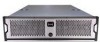
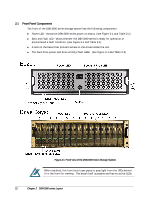
2.1 Front Panel Components The front of the DSN-3000 series storage system has the following components: Power LED - shows the DSN-3000 series power on status. (see Figure 2-1 and Table 2-1) Boot and Fault LED - shows whether the DSN-3000 series is ready for operation or encountered a fault condition. (see Figure 2-1 and Table 2-1) A lock on the bezel that protects access to the drives inside the unit. The hard drive power and drive activity/fault LEDs. (see Figure 2-1 and Table 2-2) Figure 2-1 Front View of the DSN-3000 Series Storage System When installed, the front bezel uses pipes to pass light from the LEDs behind it to the front for viewing. The bezel itself is passive and has no active LEDs. 12 Chapter 2 DSN-3000 series Layout
-
 1
1 -
2
-
3
-
4
-
5
-
6
-
 7
7 -
 8
8 -
 9
9 -
 10
10 -
 11
11 -
 12
12 -
 13
13 -
 14
14 -
 15
15 -
 16
16 -
 17
17 -
18
-
19
-
20
-
21
-
22
-
23
-
24
-
25
-
26
-
27
-
28
-
29
-
30
-
31
-
32
-
33
-
34
-
35
-
36
-
37
-
38
-
39
-
40
-
41
-
42
 |
 |
