D-Link DSN-3400-10 Hardware Reference Guide for DSN-3200-10 Valid for fir - Page 14
Back Panel Components - 100
 |
UPC - 790069299766
View all D-Link DSN-3400-10 manuals
Add to My Manuals
Save this manual to your list of manuals |
Page 14 highlights
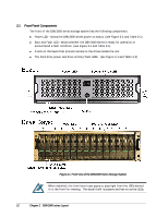
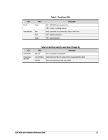
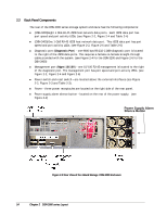
2.2 Back Panel Components The rear of the DSN-3000 series storage system enclosure has the following components: (DSN-3200)Eight 1 GbE RJ-45 iSCSI host network data ports. Each iSCSI data port has port speed and port activity LEDs. (see Figure 2-2, Figure 2-4 and Table 2-4) (DSN-3400)One 1 GbE RJ-45 iSCSI host network data port. This iSCSI data port has port speed and port activity LEDs. (see Figure 2-2, Figure 2-6 and Table 2-6) Diagnostic port (Diagnostic Port) - one 9600 bps RS-232-C DB9 diagnostic port is located to the right of the iSCSI data ports. This requires a female-to-female straight-through cable provided with the system. (see Figure 2-4 for the DSN-3200 and Figure 2-6 for the DSN-3400) Management port (Mgmt 10/100) - one 10/100 RJ-45 management is located to the right of the diagnostic port. The management port has port speed and port activity LEDs. (see Figure 2-2, Figure 2-4 and Figure 2-6) Power switch and reset switch - are located above the external interfaces (see Figure 2-2, Figure 2-3 and Table 2-3). Power - three power receptacles are located on the right side of the rear panel. Power supply alarm silence button - located on the rear of the power supply. (see Figure 2-2) Power Supply Alarm Silence Button Figure 2-2 Rear View of the xStack Storage DSN-3200 Enclosure 14 Chapter 2 DSN-3000 series Layout
-
 1
1 -
2
-
3
-
4
-
5
-
6
-
7
-
8
-
 9
9 -
 10
10 -
 11
11 -
 12
12 -
 13
13 -
 14
14 -
 15
15 -
 16
16 -
 17
17 -
 18
18 -
 19
19 -
20
-
21
-
22
-
23
-
24
-
25
-
26
-
27
-
28
-
29
-
30
-
31
-
32
-
33
-
34
-
35
-
36
-
37
-
38
-
39
-
40
-
41
-
42
 |
 |
