D-Link DSN-3400-10 Hardware Reference Guide for DSN-3200-10 Valid for fir - Page 42
A-21, Remove the Power Supply Module
 |
UPC - 790069299766
View all D-Link DSN-3400-10 manuals
Add to My Manuals
Save this manual to your list of manuals |
Page 42 highlights
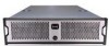
3. Remove the power supply module as shown in Figure A-21. Figure A-21 Remove the Power Supply Module 4. Insert the new power supply module by reversing the previous steps. i.e. Insert the new power supply module into the bay until it seats against the rear and the lever locks. Then screw the locking bolt into place. 42 Appendix A Replacing and Upgrading FRUs
-
 1
1 -
2
-
3
-
4
-
5
-
6
-
7
-
8
-
9
-
10
-
11
-
12
-
13
-
14
-
15
-
16
-
17
-
18
-
19
-
20
-
21
-
22
-
23
-
24
-
25
-
26
-
27
-
28
-
29
-
30
-
31
-
32
-
33
-
34
-
35
-
36
-
 37
37 -
 38
38 -
 39
39 -
 40
40 -
 41
41 -
 42
42
 |
 |

42
Appendix A Replacing and Upgrading FRUs
3.
Remove the power supply module as shown in Figure A-21.
Figure A-21
Remove the Power Supply Module
4.
Insert the new power supply module by reversing the previous steps.
i.e. Insert the
new power supply module into the bay until it seats against the rear and the lever
locks.
Then screw the locking bolt into place.