D-Link DXS-3600-EM-STACK Hardware Installation Guide - Page 10
LED Indicators
 |
View all D-Link DXS-3600-EM-STACK manuals
Add to My Manuals
Save this manual to your list of manuals |
Page 10 highlights
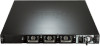
DXS-3600 Series 10GbE Layer 2/3 Switch Hardware Installation Guide LED Indicators Located on the front panel of the switch are LED indicators: Power1, Power2, MGMT, Console, Fan1, Fan2, Fan3, and SD. Additionally, the DXS-3600-32S also has a Seven segment stacking ID LED. For each SFP+ port there is a Link/ Act light. Figure 1-3 LED indicators for the DXS-3600-16S LED Power1, Power2 Management (MGMT) Console Fan1, Fan2, Fan3 SD Figure 1-4 LED indicators for the DXS-3600-32S Description This LED will light solid green after the Switch has been powered on successfully. This LED will light solid orange if the Switch's power supply fails. This LED will be off when the Switch is no longer receiving power (i.e. powered off). This LED will light solid green after a link to the management port was successfully established. This LED will blink when activity on this port is taking place. This LED will be off when there is no link present or when this interface was shutdown from within the switch's configuration. This LED will blink green during the Power-On Self Test (POST). This LED will light solid green when a user is logged in through the console port. This LED will be off after the POST finished successfully and no user is connected to the console port. This LED will light solid green when the fan is operating normally. This LED will light solid orange when the switch is booting up or when a diagnostics test is taking place. This LED will blink orange when a fan fails. This LED will be off when the fan is not receiving power. This LED will light solid green if a Secure Digital (SD) card is plugged in. This LED will blink green when the Switch is reading or writing data to and from the SD card. This LED will be off when no SD card is plugged into the SD port. This LED will light solid red when an SD card failure has been detected. 4
-
 1
1 -
2
-
3
-
4
-
 5
5 -
 6
6 -
 7
7 -
 8
8 -
 9
9 -
 10
10 -
 11
11 -
 12
12 -
 13
13 -
 14
14 -
 15
15 -
16
-
17
-
18
-
19
-
20
-
21
-
22
-
23
-
24
-
25
-
26
-
27
-
28
-
29
-
30
-
31
-
32
-
33
-
34
-
35
-
36
 |
 |
