D-Link DXS-3600-EM-STACK Hardware Installation Guide - Page 11
Rear Panel Description
 |
View all D-Link DXS-3600-EM-STACK manuals
Add to My Manuals
Save this manual to your list of manuals |
Page 11 highlights
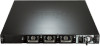
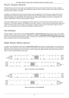
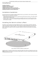
LED Link/Act LEDs Stacking ID DXS-3600 Series 10GbE Layer 2/3 Switch Hardware Installation Guide Description This LED will light solid green when there is a secure connection to a 10Gbps Ethernet device at any of the ports. This LED will light solid orange when there is a secure connection to a 1Gbps Ethernet device at any of the ports. This LED will blink green when a 10Gbps port is active, or blink orange when a 1Gbps port is active. This LED will be off when there is no link or activity. This 7-segment LED can display numbers from 1 to 12 and the following letters H, h, E, and G. The stacking ID (1 to 12) can be assigned manually by the user or automatically by the system. The letter 'H' will be displayed if this switch is the master switch in the stack. The letter 'h' will be displayed if this switch is the backup master switch in the stack. The letter 'E' will be displayed if there was an error in the system's self-test. The letter 'G' will be displayed when the Safeguard engine entered the exhausted mode. Please refer to the "LED Indicators" section in the Appendix A for more LED information. Rear Panel Description Located on the rear panel of the switch are two power supply module slots and three fan module slots. One power supply module and three fan modules are included in the package for this switch. Any additional power supply module or fan module needs to be bought separately. This switch also supports the use of a DC power supply module. PO WE R 1 100-240 VAC 50-60H z 1.7 A MAX or 4.0 A FA N 3 FA N2 FA N 1 Figure 1-5 Rear panel view of the DXS-3600-16S POWER 1 100-240 VAC 50-60Hz 1.7 A MAX or 4.0 A POWER 1 100-240 VAC 50-60Hz 2.3 A MAX or 5.2 A FA N 3 FA N 2 FA N 1 POWER 1 100-240 VAC 50-60Hz 2.3 A MAX or 5.2 A Figure 1-6 Rear panel view of the DXS-3600-32S Ports that can be found on the rear panel of this switch are listed in the table below. Port Description Two Power Supply Module These slots can be equipped with 4 kinds of additional modules. Only one power Slots supply module is included. Any additional modules should be bought seperately. • DXS-3600-PWR-FB (300 Watt, AC PSU tray with Front-to-Back airflow) • DXS-3600-PWR-BF (300 Watt, AC PSU tray with Back-to-Front airflow) • DXS-3600-PWRDC-FB (300 Watt, DC PSU tray with Front-to-Back airflow) Three Fan Module Slots These slots can be equipped with 2 kinds of additional modules. These modules are not included and should be bought seperately. • DXS-3600-FAN-FB (Normal fan tray with Front-to-Back airflow) • DXS-3600-FAN-BF (Normal fan tray with Back-to-Front airflow) 5
-
 1
1 -
2
-
3
-
4
-
5
-
 6
6 -
 7
7 -
 8
8 -
 9
9 -
 10
10 -
 11
11 -
 12
12 -
 13
13 -
 14
14 -
 15
15 -
 16
16 -
17
-
18
-
19
-
20
-
21
-
22
-
23
-
24
-
25
-
26
-
27
-
28
-
29
-
30
-
31
-
32
-
33
-
34
-
35
-
36
 |
 |