D-Link DXS-3600-EM-STACK Hardware Installation Guide - Page 15
Installing Transceivers into the Transceiver Ports
 |
View all D-Link DXS-3600-EM-STACK manuals
Add to My Manuals
Save this manual to your list of manuals |
Page 15 highlights
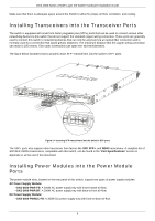
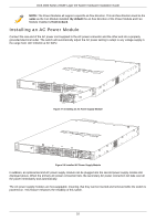
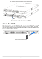
DXS-3600 Series 10GbE Layer 2/3 Switch Hardware Installation Guide Make sure that there is adequate space around the Switch to allow for proper air flow, ventilation, and cooling. Installing Transceivers into the Transceiver Ports The switch is equipped with small form-factor pluggable plus (SFP+) ports that can be used to connect various other networking devices to this switch that do not support the standard copper wiring connection. These ports are generally used to connect this switch to networking devices that can only be accessed via an optical fiber connection and is normally used for a connection that spans greater distances. The maximum distance that the copper wiring connection can reach is 100 meters. Fiber optic connections can span over several kilometers. The figure below illustrates how to properly insert SFP+ transceivers into the switch's SFP+ ports. Figure 2-4 Inserting SFP transceivers into the Switch's SFP ports The SFP+ ports also support other transceiver form factors like SFP, SFP+, and WDM transceivers. A complete list of SFP/SFP+/WDM transceivers, compatible with this switch, can be found in the "Port Specifications" section in Appendix A, at the end of this document. Installing Power Modules into the Power Module Ports The power module slots, located on the rear panel of this switch, support two types of power supply modules. AC Power Supply Module: • DXS-3600-PWR-FB: A 300W AC power supply tray with front-to-back air-flow. • DXS-3600-PWR-BF: A 300W AC power supply tray with back-to-front air-flow. DC Power Supply Module: • DXS-3600-PWRDC-FB: A 300W DC power supply tray with front-to-back air-flow. 9
-
 1
1 -
2
-
3
-
4
-
5
-
6
-
7
-
8
-
9
-
 10
10 -
 11
11 -
 12
12 -
 13
13 -
 14
14 -
 15
15 -
 16
16 -
 17
17 -
 18
18 -
 19
19 -
 20
20 -
21
-
22
-
23
-
24
-
25
-
26
-
27
-
28
-
29
-
30
-
31
-
32
-
33
-
34
-
35
-
36
 |
 |
