D-Link DXS-3600-EM-STACK Hardware Installation Guide - Page 12
Power Supply Module, Fan Module, Side Panel Description
 |
View all D-Link DXS-3600-EM-STACK manuals
Add to My Manuals
Save this manual to your list of manuals |
Page 12 highlights
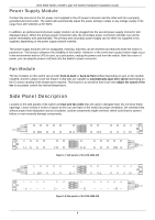
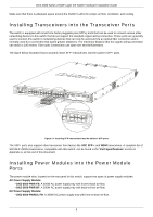
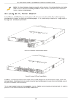
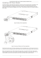
DXS-3600 Series 10GbE Layer 2/3 Switch Hardware Installation Guide Power Supply Module Connect the one end of the AC power cord supplied to the AC power connector and the other end into a properly grounded electrical outlet. The switch will automatically adjust the power setting to adapt to any voltage supply in the range from 100~240VAC at 50~60Hz. In addition, an optional second power supply module can be plugged into the second power supply connector slot displayed above. When the primary power connection fails, the secondary power connection will take over all the power immediately and automatically. The primary and secondary power supply can be either AC supplied or DC supplied, depending on the power supply module inserted. The power supply modules are hot-swappable, meaning, that they can be inserted and removed while the switch is powered on. This feature enhances the reliability of this switch. However, in the event that a power failure might occur in the environment and no UPS is used, as a precaution, unplug the power cord from the switch. After the return of power, you can plug the power cord back into the Switch's power connector. Fan Module The fan modules on this switch can provide front-to-back or back-to-front airflow depending on type on fan module installed. Another unique smart fan feature is that fans are capable to automatically ajust their speed depending on the IC sensor reading of the temperature required. This feature is so sensitive that it can even adjust the speed of the fan to accurately control the internal temperature. Side Panel Description Located on the side panels of the switch are heat and fan vents that are used to dissipate heat. Do not block these openings. Leave at least 4 inches of space at the rear and sides of the switch for proper ventilation. Be reminded that without proper heat dissipation and air circulation, system components might overheat, which could lead to system failure or even severely damage components. Figure 1-7 Side panels of the DXS-3600-16S Figure 1-8 Side panels of the DXS-3600-32S 6
-
 1
1 -
2
-
3
-
4
-
5
-
6
-
 7
7 -
 8
8 -
 9
9 -
 10
10 -
 11
11 -
 12
12 -
 13
13 -
 14
14 -
 15
15 -
 16
16 -
 17
17 -
18
-
19
-
20
-
21
-
22
-
23
-
24
-
25
-
26
-
27
-
28
-
29
-
30
-
31
-
32
-
33
-
34
-
35
-
36
 |
 |
