Dell Alienware Area-51 Threadripper Edition R7 Service Manual - Page 52
Removing the drive-bay heat sensor cable, Prerequisites, Procedure
 |
View all Dell Alienware Area-51 Threadripper Edition R7 manuals
Add to My Manuals
Save this manual to your list of manuals |
Page 52 highlights
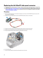
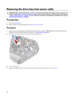
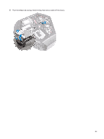
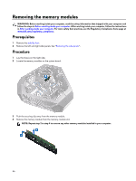
Removing the drive-bay heat sensor cable WARNING: Before working inside your computer, read the safety information that shipped with your computer and follow the steps in Before working inside your computer. After working inside your computer, follow the instructions in After working inside your computer. For more safety best practices, see the Regulatory Compliance home page at www.dell.com/regulatory_compliance. Prerequisites 1 Remove the stability foot. 2 Remove the left and right side-panels. See "Removing the side panels". Procedure 1 Lay the chassis on the right side. Locate the drive-bay heat-sensor connector (SENSOR2) on the system board. For more information on the drive-bay heat-sensor connector, see "system-board components". 2 Disconnect the drive-bay heat-sensor cable from the system board. 3 Turn the chassis over. 4 Remove the cable through the slot on the chassis. Locate the drive-bay heat-sensor. See "right view". 52
-
 1
1 -
2
-
3
-
4
-
5
-
6
-
7
-
8
-
9
-
10
-
11
-
12
-
13
-
14
-
15
-
16
-
17
-
18
-
19
-
20
-
21
-
22
-
23
-
24
-
25
-
26
-
27
-
28
-
29
-
30
-
31
-
32
-
33
-
34
-
35
-
36
-
37
-
38
-
39
-
40
-
41
-
42
-
43
-
44
-
45
-
46
-
 47
47 -
 48
48 -
 49
49 -
 50
50 -
 51
51 -
 52
52 -
 53
53 -
 54
54 -
 55
55 -
 56
56 -
 57
57 -
58
-
59
-
60
-
61
-
62
-
63
-
64
-
65
-
66
-
67
-
68
-
69
-
70
-
71
-
72
-
73
-
74
-
75
-
76
-
77
-
78
-
79
-
80
-
81
-
82
-
83
-
84
-
85
-
86
-
87
-
88
-
89
-
90
-
91
-
92
-
93
-
94
-
95
-
96
-
97
-
98
-
99
-
100
-
101
-
102
-
103
-
104
-
105
-
106
-
107
-
108
-
109
-
110
-
111
-
112
-
113
-
114
-
115
-
116
-
117
-
118
-
119
-
120
-
121
-
122
-
123
-
124
-
125
-
126
-
127
-
128
-
129
-
130
-
131
-
132
-
133
-
134
-
135
-
136
-
137
-
138
-
139
-
140
 |
 |