Dell Alienware Area-51 Threadripper Edition R7 Service Manual - Page 86
Replacing the processor liquid-cooling assembly, Procedure
 |
View all Dell Alienware Area-51 Threadripper Edition R7 manuals
Add to My Manuals
Save this manual to your list of manuals |
Page 86 highlights
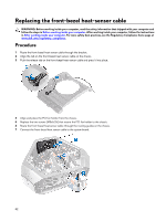
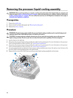
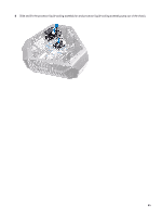
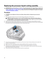
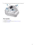
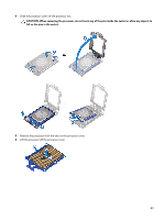
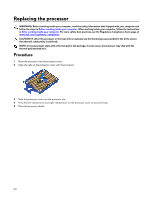
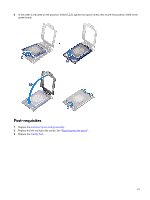
Replacing the processor liquid-cooling assembly WARNING: Before working inside your computer, read the safety information that shipped with your computer and follow the steps in Before working inside your computer. After working inside your computer, follow the instructions in After working inside your computer. For more safety best practices, see the Regulatory Compliance home page at www.dell.com/regulatory_compliance. Procedure CAUTION: Incorrect alignment of the processor liquid-cooling assembly can damage the system board and processor. 1 Apply thermal grease between the processor liquid-cooling assembly pump and the processor. NOTE: The original thermal grease can be reused if the original processor and processor liquid-cooling are reinstalled together. If either the processor or the processor liquid-cooling is replaced, use the thermal grease provided in the kit to ensure that thermal conductivity is achieved. 2 Hold the processor liquid-cooling assembly pump in one hand and processor liquid-cooling assembly fan in another. 3 Align the processor liquid-cooling assembly pump over the processor, while holding the processor liquid-cooling assembly fan outside the chassis and secure the processor liquid-cooling assembly pump. 4 Connect the processor liquid-cooling assembly fan and the processor liquid-cooling assembly pump-fan cable to the connectors on the system board. 5 Align the screw holes on the processor liquid-cooling assembly fan with the screw holes on the chassis. 6 Replace the four screws (#6-32x6) that secure the processor liquid-cooling assembly fan to the chassis. 7 In sequential order as indicated on the processor cooling-assembly, tighten the captive screws that secure the processor liquid-cooling assembly to the system board. 8 Connect the processor liquid-cooling assembly fan cable to the system board. 86
-
 1
1 -
2
-
3
-
4
-
5
-
6
-
7
-
8
-
9
-
10
-
11
-
12
-
13
-
14
-
15
-
16
-
17
-
18
-
19
-
20
-
21
-
22
-
23
-
24
-
25
-
26
-
27
-
28
-
29
-
30
-
31
-
32
-
33
-
34
-
35
-
36
-
37
-
38
-
39
-
40
-
41
-
42
-
43
-
44
-
45
-
46
-
47
-
48
-
49
-
50
-
51
-
52
-
53
-
54
-
55
-
56
-
57
-
58
-
59
-
60
-
61
-
62
-
63
-
64
-
65
-
66
-
67
-
68
-
69
-
70
-
71
-
72
-
73
-
74
-
75
-
76
-
77
-
78
-
79
-
80
-
 81
81 -
 82
82 -
 83
83 -
 84
84 -
 85
85 -
 86
86 -
 87
87 -
 88
88 -
 89
89 -
 90
90 -
 91
91 -
92
-
93
-
94
-
95
-
96
-
97
-
98
-
99
-
100
-
101
-
102
-
103
-
104
-
105
-
106
-
107
-
108
-
109
-
110
-
111
-
112
-
113
-
114
-
115
-
116
-
117
-
118
-
119
-
120
-
121
-
122
-
123
-
124
-
125
-
126
-
127
-
128
-
129
-
130
-
131
-
132
-
133
-
134
-
135
-
136
-
137
-
138
-
139
-
140
 |
 |