Dell Alienware Aurora R13 Service Manual - Page 37
Coin-cell battery, Removing the coin-cell battery
 |
View all Dell Alienware Aurora R13 manuals
Add to My Manuals
Save this manual to your list of manuals |
Page 37 highlights
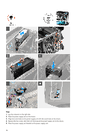
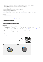
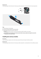
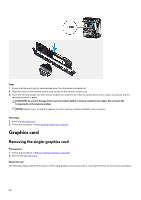
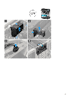
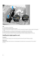
6. Replace the two screws (#6-32x1/4") that secure the power-supply unit bracket to the power-supply unit. 7. Replace the graphics-card bracket and slide the release latch to the lock position. 8. Place the power-supply unit cables back into the plastic cable clip. 9. Connect the power-supply cables to the system board. 10. Connect the graphics-card power cables to the power-supply unit. 11. Place the computer in an upright position. 12. Place the power-supply unit cables back to the routing guide on the right side of the computer. 13. Connect the power-supply unit cables to the power-supply unit extension cables on the right side of the computer. Next steps 1. Install the right-side cover. 2. Install the top cover. 3. Install the left-side cover. 4. Follow the procedure in After working inside your computer. Coin-cell battery Removing the coin-cell battery Prerequisites 1. Follow the procedure in Before working inside your computer. WARNING: Before working inside your computer, read the safety information that is shipped with your computer. For more safety best practices, see the Regulatory Compliance home page at www.dell.com/regulatory_compliance. CAUTION: Removing the coin-cell battery resets the BIOS setup program's settings to default. It is recommended that you note the BIOS setup program's settings before removing the coin-cell battery. 2. Remove the left-side cover. About this task The following images indicate the location of the coin-cell battery and provide a visual representation of the removal procedure. 37
-
 1
1 -
2
-
3
-
4
-
5
-
6
-
7
-
8
-
9
-
10
-
11
-
12
-
13
-
14
-
15
-
16
-
17
-
18
-
19
-
20
-
21
-
22
-
23
-
24
-
25
-
26
-
27
-
28
-
29
-
30
-
31
-
 32
32 -
 33
33 -
 34
34 -
 35
35 -
 36
36 -
 37
37 -
 38
38 -
 39
39 -
 40
40 -
 41
41 -
 42
42 -
43
-
44
-
45
-
46
-
47
-
48
-
49
-
50
-
51
-
52
-
53
-
54
-
55
-
56
-
57
-
58
-
59
-
60
-
61
-
62
-
63
-
64
-
65
-
66
-
67
-
68
-
69
-
70
-
71
-
72
-
73
-
74
-
75
-
76
-
77
-
78
-
79
-
80
-
81
-
82
-
83
-
84
-
85
-
86
-
87
-
88
-
89
-
90
-
91
-
92
-
93
-
94
-
95
-
96
-
97
-
98
-
99
-
100
-
101
-
102
-
103
-
104
-
105
 |
 |