Dell Alienware Aurora R13 Service Manual - Page 59
Processor, Removing the processor
 |
View all Dell Alienware Aurora R13 manuals
Add to My Manuals
Save this manual to your list of manuals |
Page 59 highlights
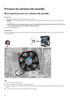
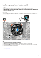
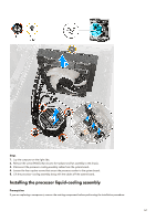
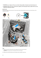
3. Align the screw holes on the processor cooler with the screw holes on the system board. 4. Tighten the four captive screws that secure the processor cooler to the system board. 5. Connect the processor-cooling assembly cables to the system board. Next steps 1. Install the left-side cover. 2. Follow the procedure in After working inside your computer. Processor Removing the processor Prerequisites 1. Follow the procedure in Before working inside your computer. 2. Remove the left-side cover. 3. Remove the processor liquid-cooling assembly or processor fan and heat-sink assembly, as applicable. About this task The following images indicate the location of the processor and provide a visual representation of the removal procedure. 59
-
 1
1 -
2
-
3
-
4
-
5
-
6
-
7
-
8
-
9
-
10
-
11
-
12
-
13
-
14
-
15
-
16
-
17
-
18
-
19
-
20
-
21
-
22
-
23
-
24
-
25
-
26
-
27
-
28
-
29
-
30
-
31
-
32
-
33
-
34
-
35
-
36
-
37
-
38
-
39
-
40
-
41
-
42
-
43
-
44
-
45
-
46
-
47
-
48
-
49
-
50
-
51
-
52
-
53
-
 54
54 -
 55
55 -
 56
56 -
 57
57 -
 58
58 -
 59
59 -
 60
60 -
 61
61 -
 62
62 -
 63
63 -
 64
64 -
65
-
66
-
67
-
68
-
69
-
70
-
71
-
72
-
73
-
74
-
75
-
76
-
77
-
78
-
79
-
80
-
81
-
82
-
83
-
84
-
85
-
86
-
87
-
88
-
89
-
90
-
91
-
92
-
93
-
94
-
95
-
96
-
97
-
98
-
99
-
100
-
101
-
102
-
103
-
104
-
105
 |
 |

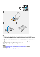
3.
Align the screw holes on the processor cooler with the screw holes on the system board.
4.
Tighten the four captive screws that secure the processor cooler to the system board.
5.
Connect the processor-cooling assembly cables to the system board.
Next steps
1.
Install the
left-side cover
.
2.
Follow the procedure in
After working inside your computer
.
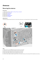
Processor
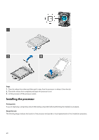
Removing the processor
Prerequisites
1.
Follow the procedure in
Before working inside your computer
.
2.
Remove the
left-side cover
.
3.
Remove the
processor liquid-cooling assembly
or
processor fan and heat-sink assembly
, as applicable.
About this task
The following images indicate the location of the processor and provide a visual representation of the removal procedure.
59