Dell DS-32M2 Installation Guide - Page 18
Installing the Switch in the Rack/Cabinet
 |
View all Dell DS-32M2 manuals
Add to My Manuals
Save this manual to your list of manuals |
Page 18 highlights
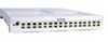
Installing the DS-16M2 and DS-32M2 Switches ! CAUTION The kits include two (2) sets of screws. To avoid damaging the screw holes, be sure to check the labeling on the bags and use the appropriate set of screws for your chassis. The chassis product number is located on labels at the back and on the bottom of the chassis. Align middle hole first 3. Secure the bracket with five 6-32 x .31 flat-head screws (see the table on page 3). Tighten the screws fully. Fan end of switch 4. Repeat steps 1 through 3 above for the other side of the switch. Installing the Switch in the Rack/Cabinet Follow the steps below to install the switch in the rack/cabinet. 1. Lift and orient the switch so that the fan end is to the front of the rack/cabinet. 2. Align the bracket on each side of the switch with the C channel on each fixed rail. 3. Push the switch about 3/4 of the way into the rack/cabinet. 4. Tighten the rear screws securing the rails to the rear of the rack/cabinet. 18 EMC Departmental Switches DS-16M2 and DS-32M2 Installation Guide
-
 1
1 -
2
-
3
-
4
-
5
-
6
-
7
-
8
-
9
-
10
-
11
-
12
-
 13
13 -
 14
14 -
 15
15 -
 16
16 -
 17
17 -
 18
18 -
 19
19 -
 20
20 -
 21
21 -
 22
22
 |
 |
