Dell Dimension 2400C User Guide - Page 61
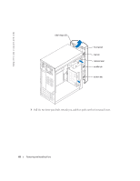
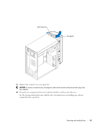
Remove two extra alignment screws, shown in the illustration on from the front
 |
View all Dell Dimension 2400C manuals
Add to My Manuals
Save this manual to your list of manuals |
Page 61 highlights
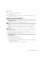
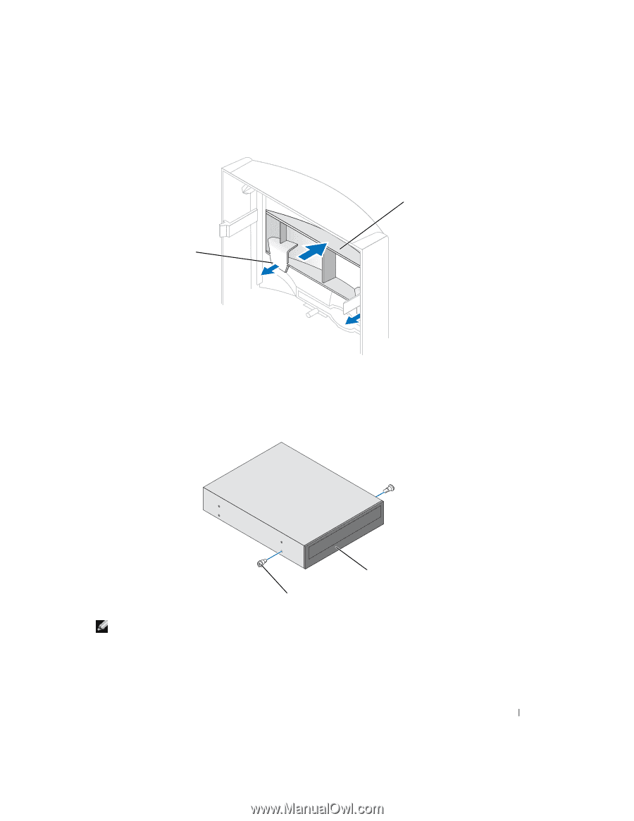
tabs (2) insert 8 Ensure that the jumper setting on the new drive is set for "cable select" (see the documentation that came with the drive for information). 9 Remove two extra alignment screws, shown in the illustration on page 62, from the front of the computer and insert them into the drive. drive alignment screws (2) NOTE: Some computers come with only two extra alignment screws; others come with four. You only need two alignment screws for this procedure. Removing and Installing Parts 61
-
 1
1 -
2
-
3
-
4
-
5
-
6
-
7
-
8
-
9
-
10
-
11
-
12
-
13
-
14
-
15
-
16
-
17
-
18
-
19
-
20
-
21
-
22
-
23
-
24
-
25
-
26
-
27
-
28
-
29
-
30
-
31
-
32
-
33
-
34
-
35
-
36
-
37
-
38
-
39
-
40
-
41
-
42
-
43
-
44
-
45
-
46
-
47
-
48
-
49
-
50
-
51
-
52
-
53
-
54
-
55
-
 56
56 -
 57
57 -
 58
58 -
 59
59 -
 60
60 -
 61
61 -
 62
62 -
 63
63 -
 64
64 -
 65
65 -
 66
66 -
67
-
68
-
69
-
70
-
71
-
72
-
73
-
74
-
75
-
76
-
77
-
78
-
79
-
80
-
81
-
82
-
83
-
84
-
85
-
86
-
87
-
88
-
89
-
90
-
91
-
92
-
93
-
94
-
95
-
96
-
97
-
98
-
99
-
100
 |
 |
Removing and Installing Parts
61
8
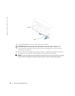
Ensure that the jumper setting on the new drive is set for "cable select" (see the
documentation that came with the drive for information).
9
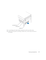
Remove two extra alignment screws, shown in the illustration on page 62, from the front of
the computer and insert them into the drive.
NOTE:
Some computers come with only two extra alignment screws; others come with four. You only
need two alignment screws for this procedure.
tabs (2)
insert
drive
alignment screws (2)