Dell EqualLogic PS6210XV PS6210 Hardware Owners Manual - Page 13
Maintaining Drives, About Drive Types, Identifying Failed Drives, Interpreting Drive LEDs
 |
View all Dell EqualLogic PS6210XV manuals
Add to My Manuals
Save this manual to your list of manuals |
Page 13 highlights
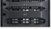
2 Maintaining Drives You can replace a failed drive while the array remains running. About Drive Types Depending on your configuration, your array supports up to 24 2.5-inch SAS and SSD drives or up to 24 3.5-inch SAS or NL-SAS drives in internal drive bays. Drives are connected to a backplane through drive carriers and are hot-swappable. Drives are supplied in a carrier that is keyed to fit into specific array models, and cannot be installed in other Dell arrays, or arrays not from Dell Inc. Dell uses specially qualified and tested hard drives for its EqualLogic storage systems, and manages hard drive quality and firmware only for those drives. As a result, only Dell-provided hard drives are supported by PS Series arrays. Attempts to use other, unapproved hard drives in the PS6210 array will not be successful. Identifying Failed Drives A drive failure is indicated by: • LEDs on the drive. See Interpreting Drive LEDs on page 7. • A message on the console, in the event log, or in the Group Manager Alarms panel. • Indications in the Group Manager Member Disks window or the CLI member select show disks command output. Behind the bezel, arrays have a label showing the drive numbering for that specific array model: • In arrays with 2.5-inch drives (installed vertically in a row), the drives are numbered 0-23, left to right. • In arrays with 3.5-inch drives (installed horizontally), the drives are numbered from left to right and top to bottom, starting with 0 on the upper left side. Table 3 shows the drive order for the 3.5inch drives. Table 3: 3.5-inch Drive Numbering 0123 4567 8 9 10 11 12 13 14 15 16 17 18 19 20 21 22 23 Interpreting Drive LEDs The LEDs on a 3.5-inch drive are shown in Figure 8. The LEDs on a 2.5-inch drive are shown in Figure 9. Drive LED states are described in Table 4. 7
-
 1
1 -
2
-
3
-
4
-
5
-
6
-
7
-
 8
8 -
 9
9 -
 10
10 -
 11
11 -
 12
12 -
 13
13 -
 14
14 -
 15
15 -
 16
16 -
 17
17 -
 18
18 -
19
-
20
-
21
-
22
-
23
-
24
-
25
-
26
-
27
-
28
-
29
-
30
-
31
-
32
-
33
-
34
-
35
-
36
-
37
-
38
-
39
-
40
-
41
-
42
-
43
-
44
-
45
-
46
-
47
-
48
 |
 |
