Dell External OEMR XL R610 Technical Guide - Page 47
Cable Management Arm CMA, Rack View
 |
View all Dell External OEMR XL R610 manuals
Add to My Manuals
Save this manual to your list of manuals |
Page 47 highlights
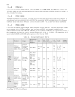
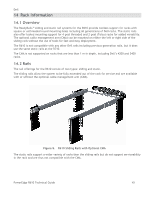
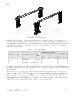
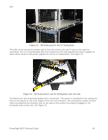
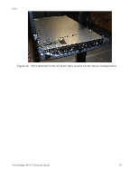
Dell Product R610 Table 15. Rail Adjustability Ranges and Depth Rail Mounting ID Interface Rail Type A1 ReadyRails™ Sliding A2 ReadyRails™/ Generic Static Rail Adjustability Range (mm) Rail Depth (mm) Square Round Threaded Without With Min Max Min Max Min Max CMA CMA 692 756 678 749 - - 768 887 588 828 574 821 592 846 608 - The adjustment range of the rails is a function of the type of rack in which they are being mounted. The min-max values listed above represent the allowable distance between the front and rear mounting flanges in the rack. Rail depth represents the minimum depth of the rail as measured from the rack front mounting flanges when the rail rear bracket is positioned all the way forward. 14.3 Cable Management Arm (CMA) The optional cable management arm (CMA) for the R610 organizes and secures the cords and cables exiting the back of the server and unfolds to allow the server to extend out of the rack without having to detach the cables. Some key features of the R610 CMA include: Large U-shaped baskets support dense cable loads. An open vent pattern allows for optimal airflow. The CMA mounting is fully-reversible (can be mounted on either side) with no conversion required. Hook-and-loop straps are used rather than plastic tie wraps to eliminate the risk of cable damage during cycling. A low-profile fixed tray is provided to both support and retain the CMA in its fully closed position. The CMA and the tray mount without the use of tools using simple and intuitive snap-in designs. 14.4 Rack View The R610 sliding rails are a drop-in design, meaning that the system is installed vertically into the rails by inserting the shoulder nuts on the sides of the system into the J-slots in the inner rail members with the rails in the fully extended position. See Figure 11. PowerEdge R610 Technical Guide 47
-
 1
1 -
2
-
3
-
4
-
5
-
6
-
7
-
8
-
9
-
10
-
11
-
12
-
13
-
14
-
15
-
16
-
17
-
18
-
19
-
20
-
21
-
22
-
23
-
24
-
25
-
26
-
27
-
28
-
29
-
30
-
31
-
32
-
33
-
34
-
35
-
36
-
37
-
38
-
39
-
40
-
41
-
 42
42 -
 43
43 -
 44
44 -
 45
45 -
 46
46 -
 47
47 -
 48
48 -
 49
49 -
 50
50 -
 51
51 -
 52
52 -
53
-
54
-
55
-
56
-
57
-
58
-
59
-
60
-
61
 |
 |
