Dell Inspiron 1428 Service Manual - Page 29
Memory Modules - service manual
 |
View all Dell Inspiron 1428 manuals
Add to My Manuals
Save this manual to your list of manuals |
Page 29 highlights
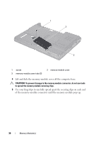
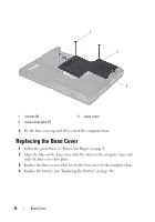
8 Memory Module(s) WARNING: Before working inside your computer, read the safety information that shipped with your computer. For additional safety best practices information, see the Regulatory Compliance Homepage at www.dell.com/regulatory_compliance. CAUTION: To avoid electrostatic discharge, ground yourself by using a wrist grounding strap or by periodically touching an unpainted metal surface (such as a connector on your computer). CAUTION: Only a certified service technician should perform repairs on your computer. Damage due to servicing that is not authorized by Dell™ is not covered by your warranty. CAUTION: To help prevent damage to the system board, remove the main battery (see "Removing the Battery" on page 13) before working inside the computer. You can increase your computer memory by installing memory modules on the system board. See "Basic Specifications" in your Setup Guide or the Comprehensive Specifications at support.dell.com\manuals for information on the type of memory supported by your computer. NOTE: Memory modules purchased from Dell are covered under your computer warranty. Your computer has two user-accessible SODIMM sockets that can be accessed from the bottom of the computer. The DIMM B memory module is located directly above the DIMM A memory module located on the bottom of the computer. NOTE: If you need to install memory modules in two connectors, install a memory module in the DIMM A connector before you install a module in the DIMM B connector. Removing the Memory Module(s) 1 Follow the procedures in "Before You Begin" on page 9. 2 Remove the battery (see "Removing the Battery" on page 13). 3 Remove the screw that secures the memory-module cover to the computer base. Memory Module(s) 29
-
 1
1 -
2
-
3
-
4
-
5
-
6
-
7
-
8
-
9
-
10
-
11
-
12
-
13
-
14
-
15
-
16
-
17
-
18
-
19
-
20
-
21
-
22
-
23
-
 24
24 -
 25
25 -
 26
26 -
 27
27 -
 28
28 -
 29
29 -
 30
30 -
 31
31 -
 32
32 -
 33
33 -
 34
34 -
35
-
36
-
37
-
38
-
39
-
40
-
41
-
42
-
43
-
44
-
45
-
46
-
47
-
48
-
49
-
50
-
51
-
52
-
53
-
54
-
55
-
56
-
57
-
58
-
59
-
60
-
61
-
62
-
63
-
64
-
65
-
66
-
67
-
68
-
69
-
70
-
71
-
72
-
73
-
74
-
75
-
76
-
77
-
78
-
79
-
80
-
81
-
82
 |
 |