Dell Inspiron 1428 Service Manual - Page 41
Replacing the Processor Fan and Heat Sink, Assembly
 |
View all Dell Inspiron 1428 manuals
Add to My Manuals
Save this manual to your list of manuals |
Page 41 highlights
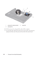
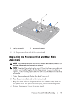
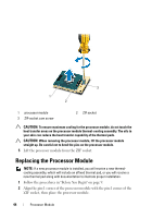
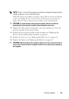
1 2 1 spring screws (4) 2 processor heat sink 8 Lift the processor heat sink off the system board. Replacing the Processor Fan and Heat Sink Assembly NOTE: This procedure assumes that you have already removed the processor fan and heat sink assembly and are ready to replace it. NOTE: The original thermal pad can be reused if the original processor module and heat sink are reinstalled together. If either the processor module or heat sink is replaced, use the thermal pad provided in the kit to ensure that thermal conductivity is achieved. 1 Follow the procedures in "Before You Begin" on page 9. 2 Place the processor heat sink on the system board. 3 Align the screw holes on the processor heat sink with the screw holes on the system board and replace the four spring screws in ascending order. 4 Replace the processor fan on the system board. Processor Fan and Heat Sink Assembly 41
-
 1
1 -
2
-
3
-
4
-
5
-
6
-
7
-
8
-
9
-
10
-
11
-
12
-
13
-
14
-
15
-
16
-
17
-
18
-
19
-
20
-
21
-
22
-
23
-
24
-
25
-
26
-
27
-
28
-
29
-
30
-
31
-
32
-
33
-
34
-
35
-
 36
36 -
 37
37 -
 38
38 -
 39
39 -
 40
40 -
 41
41 -
 42
42 -
 43
43 -
 44
44 -
 45
45 -
 46
46 -
47
-
48
-
49
-
50
-
51
-
52
-
53
-
54
-
55
-
56
-
57
-
58
-
59
-
60
-
61
-
62
-
63
-
64
-
65
-
66
-
67
-
68
-
69
-
70
-
71
-
72
-
73
-
74
-
75
-
76
-
77
-
78
-
79
-
80
-
81
-
82
 |
 |
