| Section |
Page |
| Dell™ Inspiron™ 1428 Service Manual |
1 |
| Notes, Cautions, and Warnings |
2 |
| Contents |
3 |
| 2 |
9 |
| Before You Begin |
9 |
| Recommended Tools |
9 |
| Turning Off Your Computer |
9 |
| 1 Save and close all open files and exit all open programs. |
9 |
| 2 In Microsoft® Windows® 7, click Start , click the arrow , and then click Shut Down. |
9 |
| 3 Ensure that the computer and any attached devices are turned off. If your computer and attached devices did not automatically ... |
9 |
| Before Working Inside Your Computer |
10 |
| 1 Ensure that the work surface is flat and clean to prevent the computer cover from being scratched. |
10 |
| 2 Turn off your computer (see \ |
10 |
| 3 If the computer is connected to a docking device (docked), undock it. See the documentation that came with your docking device for instructions. |
10 |
| 4 Disconnect all telephone or network cables from the computer. |
10 |
| 5 Press and eject any installed cards from the ExpressCard slot or the 3-in-1 Media Card Reader. |
10 |
| 6 Disconnect your computer and all attached devices from their electrical outlets. |
11 |
| 7 Remove the battery (see \ |
11 |
| 8 Turn the computer top-side up, open the display, and press the power button to ground the system board. |
11 |
| 3 |
13 |
| Battery |
13 |
| Removing the Battery |
13 |
| 1 Follow the procedures in \ |
13 |
| 2 Turn the computer over. |
13 |
| 3 Slide the battery lock latch to the unlock position. |
13 |
| 4 Slide the battery release latch to the side. |
13 |
| 5 Slide the battery out of the battery bay. |
13 |
| Replacing the Battery |
14 |
| 1 Follow the procedures in \ |
14 |
| 2 Slide the battery into the battery bay until it clicks into place. |
14 |
| 3 Slide the battery lock latch to the lock position. |
14 |
| 4 |
15 |
| Hinge Cover |
15 |
| Removing the Hinge Cover |
15 |
| 1 Follow the procedures in \ |
15 |
| 2 Remove the battery (see \ |
15 |
| 3 Turn the computer over and open the display as far as possible. |
15 |
| 4 Insert a plastic scribe and gently pry the hinge cover up. Ease the hinge cover out moving from right to left, and remove the cover. |
15 |
| Replacing the Hinge Cover |
16 |
| 1 Follow the procedures in \ |
16 |
| 2 Align the tabs on the hinge cover with the slots on the palm rest and snap the cover in place. |
16 |
| 3 Replace the battery (see \ |
16 |
| 5 |
17 |
| Keyboard |
17 |
| Removing the Keyboard |
17 |
| 1 Follow the procedures in \ |
17 |
| 2 Remove the battery (see \ |
17 |
| 3 Remove the hinge cover (see \ |
17 |
| 4 Remove the two screws that secure the keyboard to the palm rest. |
17 |
| 5 Carefully lift the keyboard and slide the keyboard tabs out of the slots on the computer. Turn the keyboard over as indicated in the following illustration. |
18 |
| 6 Lift the keyboard connector latch and disconnect the keyboard cable from the system board connector. |
19 |
| 7 Lift the keyboard off the palm rest. |
19 |
| Replacing the Keyboard |
19 |
| 1 Follow the procedures in \ |
19 |
| 2 Slide the keyboard cable into the connector on the system board and press down on the keyboard cable connector latch to secure the keyboard cable. |
19 |
| 3 Align the six tabs on the keyboard with the slots on the palm rest. |
19 |
| 4 Place the keyboard on the palm rest. |
19 |
| 5 Replace the two screws that secure the keyboard to the palm rest. |
19 |
| 6 Replace the hinge cover (see \ |
19 |
| 7 Replace the battery (see \ |
19 |
| 6 |
21 |
| Hard Drive |
21 |
| Removing the Hard Drive |
22 |
| 1 Follow the procedures in \ |
22 |
| 2 Remove the battery (see \ |
22 |
| 3 Remove the two screws that secure the hard-drive cover to the computer base. |
22 |
| 4 Pry out the hard-drive cover using your finger. |
22 |
| 5 Remove the two screws that secure the hard-drive assembly to the computer base. |
22 |
| 6 Pull the pull-tab on the hard-drive assembly towards the right to disconnect the hard-drive assembly from the system board connector. |
22 |
| 7 Lift the hard-drive assembly out of the computer base. |
22 |
| 8 Remove the four screws that secure the hard drive to the hard-drive cage. |
23 |
| 9 Lift the hard-drive cage away from the hard drive. |
24 |
| Replacing the Hard Drive |
24 |
| 1 Follow the procedures in \ |
24 |
| 2 Remove the new drive from its packaging. |
24 |
| 3 Place the hard drive in the hard-drive cage. |
24 |
| 4 Replace the four screws that secure the hard drive to the hard-drive cage. |
24 |
| 5 Place the hard-drive assembly in the computer base. |
24 |
| 6 Slide and connect the hard-drive assembly to the system board connector. |
24 |
| 7 Replace the two screws that secure the hard-drive assembly to the computer base. |
24 |
| 8 Align the tabs on the hard-drive cover with the slots on the computer base and snap the hard-drive cover into place. |
24 |
| 9 Replace the two screws that secure the hard-drive cover to the computer base. |
24 |
| 10 Replace the battery (see \ |
24 |
| 11 Install the operating system for your computer, as needed (See \ |
24 |
| 12 Install the drivers and utilities for your computer, as needed. For more information, see the Dell Technology Guide. |
24 |
| 7 |
25 |
| Optical Drive |
25 |
| Removing the Optical Drive |
25 |
| 1 Follow the procedures in \ |
25 |
| 2 Remove the battery (see \ |
25 |
| 3 Remove the screw that secures the optical drive to the computer base. |
25 |
| 4 Using a plastic scribe, push the notch to remove the optical drive from the optical drive bay. |
25 |
| 5 Slide the optical drive out of the optical drive bay. |
25 |
| Replacing the Optical Drive |
26 |
| 1 Follow the procedures in \ |
26 |
| 2 Slide the optical drive into the optical drive bay until it is fully seated. |
26 |
| 3 Replace the screw that secures the optical drive to the computer base. |
26 |
| 4 Replace the battery (see \ |
26 |
| 8 |
29 |
| Memory Module(s) |
29 |
| Removing the Memory Module(s) |
29 |
| 1 Follow the procedures in \ |
29 |
| 2 Remove the battery (see \ |
29 |
| 3 Remove the screw that secures the memory-module cover to the computer base. |
29 |
| 4 Lift and slide the memory-module cover off the computer base. |
30 |
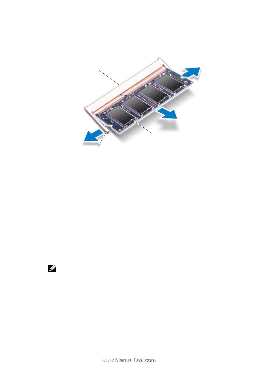
| 5 Use your fingertips to carefully spread apart the securing clips on each end of the memory-module connector until the memory module pops up. |
30 |
| 6 Remove the memory module from the memory-module connector. |
31 |
| Replacing the Memory Module(s) |
31 |
| 1 Follow the procedures in \ |
31 |
| 2 Align the notch in the memory module with the tab in the memory module connector. |
31 |
| 3 Slide the memory module firmly into the slot at a 45-degree angle, and press the memory module down until it clicks into place. If you do not hear the click, remove the memory module and reinstall it. |
31 |
| 4 Align the tabs on the memory module cover with the slots on the computer base and place the module cover in position. |
32 |
| 5 Replace the screw that secures the memory module cover to the computer base. |
32 |
| 6 Replace the battery (see \ |
32 |
| 7 Turn on the computer. |
32 |
| 9 |
33 |
| Base Cover |
33 |
| Removing the Base Cover |
33 |
| 1 Follow the procedures in \ |
33 |
| 2 Remove the battery (see \ |
33 |
| 3 Remove the three screws that secure the base cover to the computer base. |
33 |
| 4 Pry the base cover up and lift it out of the computer base. |
34 |
| Replacing the Base Cover |
34 |
| 1 Follow the procedures in \ |
34 |
| 2 Align the tabs on the base cover with the slots on the computer base and snap the base cover into place. |
34 |
| 3 Replace the three screws that secure the base cover to the computer base. |
34 |
| 4 Replace the battery (see \ |
34 |
| 10 |
35 |
| Wireless Mini-Card |
35 |
| Removing the Mini-Card |
35 |
| 1 Follow the procedures in \ |
35 |
| 2 Remove the battery (see \ |
35 |
| 3 Remove the base cover (see \ |
35 |
| 4 Disconnect the antenna cables from the Mini-Card. |
35 |
| 5 Remove the two screws that secure the Mini-Card to the system board. |
35 |
| 6 Lift the Mini-Card out of the system board connector. |
36 |
| Replacing the Mini-Card |
37 |
| 1 Follow the procedures in \ |
37 |
| 2 Remove the new Mini-Card from its packaging. |
37 |
| 3 Insert the Mini-Card connector at a 45-degree angle into the system board connector. |
37 |
| 4 Press the other end of the Mini-Card down into the slot on the system board. |
37 |
| 5 Replace the two screws that secure the Mini-Card to the system board. |
37 |
| 6 Connect the appropriate antenna cables to the Mini-Card you are installing. The following table provides the antenna cable color scheme for each Mini-Card supported by your computer. |
37 |
| 7 Replace the base cover (see \ |
38 |
| 8 Replace the battery (see \ |
38 |
| 9 Install the drivers and utilities for your computer, as required. For more information, see the Dell Technology Guide. |
38 |
| 11 |
39 |
| Processor Fan and Heat Sink Assembly |
39 |
| Removing the Processor Fan and Heat Sink Assembly |
39 |
| 1 Follow the procedures in \ |
39 |
| 2 Remove the battery (see \ |
39 |
| 3 Remove the base cover (see \ |
39 |
| 4 Disconnect processor fan cable from the system board connector. |
39 |
| 5 Remove the three screws that secure the processor fan to the system board. |
39 |
| 6 Lift the processor fan, along with the cable, off the computer. |
40 |
| 7 In sequential order (indicated on the processor heat sink), remove the four spring screws that secure the processor heat sink to the system board. |
40 |
| 8 Lift the processor heat sink off the system board. |
41 |
| Replacing the Processor Fan and Heat Sink Assembly |
41 |
| 1 Follow the procedures in \ |
41 |
| 2 Place the processor heat sink on the system board. |
41 |
| 3 Align the screw holes on the processor heat sink with the screw holes on the system board and replace the four spring screws in ascending order. |
41 |
| 4 Replace the processor fan on the system board. |
41 |
| 5 Replace the three screws that secure the processor fan to the system board. |
42 |
| 6 Connect the processor fan cable to the system board connector. |
42 |
| 7 Replace the base cover (see \ |
42 |
| 8 Replace the battery (see \ |
42 |
| 12 |
43 |
| Processor Module |
43 |
| Removing the Processor Module |
43 |
| 1 Follow the procedures in \ |
43 |
| 2 Remove the base cover (see \ |
43 |
| 3 Remove the processor fan and heat sink assembly (see \ |
43 |
| 4 To loosen the ZIF socket, use a small flat-blade screwdriver and rotate the ZIF-socket cam screw counterclockwise until it comes to the cam stop. |
43 |
| 5 Lift the processor module from the ZIF socket. |
44 |
| Replacing the Processor Module |
44 |
| 1 Follow the procedures in \ |
44 |
| 2 Align the pin-1 corner of the processor module with the pin-1 corner of the ZIF socket, then place the processor module. |
44 |
| 3 Tighten the ZIF socket by turning the cam screw clockwise to secure the processor module to the system board. |
45 |
| 4 Replace the processor fan and heat sink assembly (see \ |
45 |
| 5 Replace the base cover (see \ |
45 |
| 6 Replace the battery (see \ |
45 |
| 13 |
47 |
| Display |
47 |
| Display Assembly |
47 |
| Removing the Display Assembly |
47 |
| 1 Follow the procedures in \ |
47 |
| 2 Remove the battery (see \ |
47 |
| 3 Remove the base cover (see \ |
47 |
| 4 Disconnect the antenna cables from the Mini-Card (see \ |
47 |
| 5 Make note of the Mini-Card antenna cables routing and remove the cables from the routing guides. |
47 |
| 6 Remove the four screws that secure the display assembly to the computer base. |
47 |
| 7 Turn the computer over and remove the hinge cover (see \ |
48 |
| 8 Remove the keyboard (see \ |
48 |
| 9 Make note of the Mini-Card antenna cable routing and carefully dislodge the antenna cables from the cable routing slot on the computer. Pull the cables away, so that they are clear of the palm rest. |
48 |
| 10 Disconnect the display cable, inverter board cable, camera cable, and microphone cables from the respective system board connectors. |
48 |
| 11 Remove the cables from their routing guides. |
48 |
| 12 Remove the two screws that secure the display assembly to the computer base. |
49 |
| 13 Lift the display assembly off the computer. |
50 |
| Replacing the Display Assembly |
50 |
| 1 Follow the procedures in \ |
50 |
| 2 Place the display assembly in position and replace the two screws that secure the display assembly to the computer base. |
50 |
| 3 Route all the cables through the routing guides. |
50 |
| 4 Connect the display cable, inverter board cable, and the camera cable to their respective system board connectors. |
50 |
| 5 Connect the microphone cables to their respective connectors. |
50 |
| 6 Route the Mini-Card antenna cables, and guide the cables to the bottom of the computer through the cable routing slot. |
51 |
| 7 Replace the keyboard (see \ |
51 |
| 8 Replace the hinge cover (see \ |
51 |
| 9 Replace the four screws that secure the display assembly to the computer base. |
51 |
| 10 Connect the antenna cables to the Mini-Card (see \ |
51 |
| 11 Replace the base cover (see \ |
51 |
| 12 Replace the battery (see \ |
51 |
| Display Bezel |
51 |
| Removing the Display Bezel |
51 |
| 1 Follow the procedures in \ |
51 |
| 2 Remove the display assembly (see \ |
51 |
| 3 Remove the four rubber pads that cover the screws that secure the display bezel to the display cover. |
51 |
| 4 Remove the four screws that secure the display bezel to the display assembly. |
52 |
| 5 Using your fingertips, carefully pry up the inside edge of the display bezel. |
52 |
| 6 Remove the display bezel. |
52 |
| Replacing the Display Bezel |
52 |
| 1 Follow the procedures in \ |
52 |
| 2 Realign the display bezel over the display panel, and gently snap into place. |
52 |
| 3 Replace the four screws that secure the display bezel to the display cover. |
52 |
| 4 Replace the four rubber pads to cover the screws that secure the display bezel to the display cover. |
52 |
| 5 Replace the display assembly (see \ |
52 |
| Display Panel |
53 |
| Removing the Display Panel |
53 |
| 1 Follow the procedures in \ |
53 |
| 2 Remove the display assembly (see \ |
53 |
| 3 Remove the display bezel (see \ |
53 |
| 4 Remove the inverter board (see \ |
53 |
| 5 Remove the two screws that secure the display panel and one screw that secures the display cable to the display cover. |
53 |
| 6 Lift the display panel off the display cover. |
53 |
| Replacing the Display Panel |
54 |
| 1 Follow the procedures in \ |
54 |
| 2 Align the display panel with the display cover and replace the two screws that secure the display panel and one screw that secures the display cable to the display cover. |
54 |
| 3 Replace the inverter board (see \ |
54 |
| 4 Replace the display bezel (see \ |
54 |
| 5 Replace the display assembly (see \ |
54 |
| Display-Panel Bracket |
54 |
| Removing the Display-Panel Bracket |
54 |
| 1 Follow the procedures in \ |
54 |
| 2 Remove the display assembly (see \ |
54 |
| 3 Remove the display bezel (see \ |
54 |
| 4 Remove the inverter board (see \ |
54 |
| 5 Remove the display panel (see \ |
54 |
| 6 Remove the eight screws (four on each side) that secure the display-panel brackets to the display panel. |
55 |
| 7 Remove the display-panel brackets off the display panel. |
55 |
| Replacing the Display-Panel Bracket |
55 |
| 1 Follow the procedures in \ |
55 |
| 2 Replace the display-panel brackets. |
55 |
| 3 Replace the eight screws (four on each side) that secure the display-panel brackets to the display panel. |
55 |
| 4 Replace the display panel (see \ |
55 |
| 5 Replace the inverter board (see \ |
55 |
| 6 Replace the display bezel (see \ |
55 |
| 7 Replace the display assembly (see \ |
55 |
| Display-Panel Cable |
56 |
| Removing the Display-Panel Cable |
56 |
| 1 Follow the procedures in \ |
56 |
| 2 Remove the display assembly (see \ |
56 |
| 3 Remove the display bezel (see \ |
56 |
| 4 Remove the inverter board (see \ |
56 |
| 5 Remove the display panel (see \ |
56 |
| 6 Turn the display panel over and place it on a clean surface. |
56 |
| 7 Pull the pull-tab as shown in the illustration to disconnect the display- panel cable from the connector on the display panel. |
56 |
| Replacing the Display-Panel Cable |
57 |
| 1 Follow the procedures in \ |
57 |
| 2 Connect the display-panel cable to the connector on the display panel. |
57 |
| 3 Replace the display panel (see \ |
57 |
| 4 Replace the display bezel (see \ |
57 |
| 5 Replace the inverter board (see \ |
57 |
| 6 Replace the display assembly (\ |
57 |
| 14 |
59 |
| Inverter Board |
59 |
| Removing the Inverter Board |
59 |
| 1 Follow the procedures in \ |
59 |
| 2 Remove the battery (see \ |
59 |
| 3 Remove the display assembly (see \ |
59 |
| 4 Remove the display bezel (see \ |
59 |
| 5 Remove the screw that secures the inverter board to the display cover. |
59 |
| 6 Turn the inverter board over and disconnect the inverter board cables from the connectors on the inverter board. |
60 |
| 7 Lift the inverter board off the display cover. |
60 |
| Replacing the Inverter Board |
60 |
| 1 Follow the procedures in \ |
60 |
| 2 Connect the inverter board cables to the connectors on the inverter board. |
60 |
| 3 Turn the inverter board over and place it on the display cover. |
60 |
| 4 Replace the screw that secures the inverter board to the display cover. |
60 |
| 5 Replace the display bezel (see \ |
60 |
| 6 Replace the display assembly (see \ |
60 |
| 7 Replace the battery (see \ |
60 |
| 15 |
63 |
| Camera Module |
63 |
| Removing the Camera Module |
63 |
| 1 Follow the procedures in \ |
63 |
| 2 Remove the battery (see \ |
63 |
| 3 Remove the hinge cover (see \ |
63 |
| 4 Remove the keyboard (see \ |
63 |
| 5 Remove the display assembly (see \ |
63 |
| 6 Remove the display bezel (see \ |
63 |
| 7 Remove the inverter board (see \ |
63 |
| 8 Remove the display panel (see \ |
63 |
| 9 Remove the two screws that secure the camera module to the display cover. |
63 |
| 10 Slide the camera module towards the right to release it from the display cover. |
63 |
| 11 Turn the camera module over and disconnect the camera cable from the connector on the camera module. |
64 |
| 12 Remove the camera module. |
64 |
| Replacing the Camera Module |
64 |
| 1 Follow the procedures in \ |
64 |
| 2 Connect the camera cable to the connector on the camera module. |
64 |
| 3 Turn the camera module over and slide the notch on the camera module into the slot on the display cover. |
64 |
| 4 Replace the two screws that secure the camera module to the display cover. |
64 |
| 5 Replace the display panel (see \ |
64 |
| 6 Replace the inverter board (see \ |
64 |
| 7 Replace the display bezel (see \ |
64 |
| 8 Replace the display assembly (see \ |
65 |
| 9 Replace the keyboard (see \ |
65 |
| 10 Replace the hinge cover (see \ |
65 |
| 11 Replace the battery (see \ |
65 |
| 16 |
67 |
| Palm Rest Assembly |
67 |
| Removing the Palm Rest Assembly |
67 |
| 1 Follow the procedures in \ |
67 |
| 2 Remove the battery (see \ |
67 |
| 3 Remove the base cover (see \ |
67 |
| 4 Remove the hinge cover (see \ |
67 |
| 5 Remove the keyboard (see \ |
67 |
| 6 Remove the display assembly (see \ |
67 |
| 7 Remove the fourteen screws from the computer base. |
67 |
| 8 Turn the computer top side up and disconnect the touch pad cable, speaker cable, and power board cable from their connectors on the system board. |
68 |
| 9 Using your fingers carefully lift the palm rest assembly along the rear edge and then ease the palm rest assembly from the computer base. |
69 |
| 10 Lift the palm rest assembly off the computer base. |
70 |
| Replacing the Palm Rest Assembly |
70 |
| 1 Follow the procedures in \ |
70 |
| 2 Align the palm rest assembly on the computer base and gently snap the palm rest into place. |
70 |
| 3 Turn the computer over and replace the fourteen screws on the computer base. |
70 |
| 4 Turn the computer top side up. |
70 |
| 5 Connect the touch pad cable, speaker cable, and power board cable to their respective connectors on the system board. |
70 |
| 6 Replace the display assembly (see \ |
70 |
| 7 Replace the keyboard (see \ |
70 |
| 8 Replace the hinge cover (see \ |
70 |
| 9 Replace the base cover (see \ |
70 |
| 10 Replace the battery (see \ |
71 |
| 17 |
73 |
| System Board |
73 |
| Removing the System Board |
73 |
| 1 Follow the procedures in \ |
73 |
| 2 Remove the battery (see \ |
73 |
| 3 Remove the base cover (see \ |
73 |
| 4 Remove the hinge cover (see \ |
73 |
| 5 Remove the keyboard (see \ |
73 |
| 6 Remove the display assembly (see \ |
73 |
| 7 Remove the palm rest assembly (see \ |
73 |
| 8 Remove the optical drive (see \ |
74 |
| 9 Remove the hard drive (see \ |
74 |
| 10 Remove the memory module(s) (see \ |
74 |
| 11 Remove the Mini-Card (see \ |
74 |
| 12 Disconnect the AC adapter connector cable from the connector on the system board. |
74 |
| 13 Remove the processor fan and heat sink assembly (see \ |
74 |
| 14 Remove the processor module (see \ |
74 |
| 15 Turn the computer over and disconnect the I/O board cable and audio board cable from their respective system board connectors. |
74 |
| 16 Remove the two screws that secure the system board to the computer base. |
74 |
| 17 Lift the system board at an angle toward the side of the computer and out of the computer base. |
75 |
| 18 Turn the system board over. |
75 |
| 19 Remove the coin-cell battery (see \ |
75 |
| Replacing the System Board |
76 |
| 1 Follow the procedures in \ |
76 |
| 2 Replace the coin-cell battery (see \ |
76 |
| 3 Turn the system board over. |
76 |
| 4 Align the connectors on the system board with the slots on the computer base and place the system board on the computer base. |
76 |
| 5 Replace the two screws that secure the system board to the computer base. |
76 |
| 6 Connect the I/O board cable and the audio board cable to their respective connectors on the system board. |
76 |
| 7 Turn the computer over and connect the AC adapter connector cable to the system board connector. |
76 |
| 8 Replace the processor module (see \ |
76 |
| 9 Replace the processor fan and heat sink assembly (see \ |
77 |
| 10 Replace the Mini-Card (see \ |
77 |
| 11 Replace the memory modules (see \ |
77 |
| 12 Replace the hard drive (see \ |
77 |
| 13 Replace the optical drive (see \ |
77 |
| 14 Replace the palm rest assembly (see \ |
77 |
| 15 Replace the display assembly (see \ |
77 |
| 16 Replace the keyboard (see \ |
77 |
| 17 Replace the hinge cover (see \ |
77 |
| 18 Replace base cover (see \ |
77 |
| 19 Replace the battery (see \ |
77 |
| 20 Turn on the computer. |
77 |
| 21 Enter the service tag (see \ |
77 |
| Entering the Service Tag in the BIOS |
77 |
| 1 Ensure that the AC adapter is plugged in and that the main battery is installed properly. |
77 |
| 2 Turn on the computer. |
77 |
| 3 Press <F2> during POST to enter the system setup program. |
77 |
| 4 Navigate to the security tab and enter the service tag in the Set Service Tag field. |
77 |
| Coin-Cell Battery |
79 |
| Removing the Coin-Cell Battery |
79 |
| Replacing the Coin-Cell Battery |
80 |
 1
1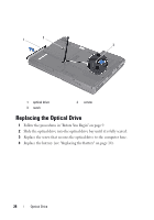 26
26 27
27 28
28 29
29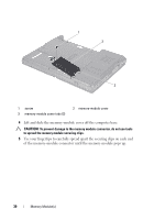 30
30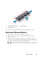 31
31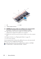 32
32 33
33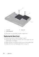 34
34 35
35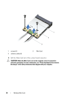 36
36