Dell Inspiron 1428 Service Manual - Page 44
Replacing the Processor Module
 |
View all Dell Inspiron 1428 manuals
Add to My Manuals
Save this manual to your list of manuals |
Page 44 highlights
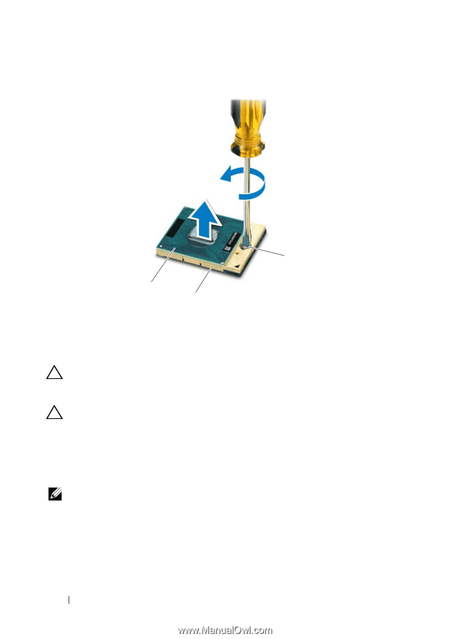
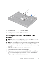
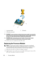
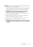
3 1 2 1 processor module 3 ZIF-socket cam screw 2 ZIF socket CAUTION: To ensure maximum cooling for the processor module, do not touch the heat transfer areas on the processor module thermal-cooling assembly. The oils in your skin can reduce the heat transfer capability of the thermal pads. CAUTION: When removing the processor module, lift the processor module straight up. Be careful not to bend the pins on the processor module. 5 Lift the processor module from the ZIF socket. Replacing the Processor Module NOTE: If a new processor module is installed, you will receive a new thermalcooling assembly, which will include an affixed thermal pad, or you will receive a new thermal pad along with documentation to illustrate proper installation. 1 Follow the procedures in "Before You Begin" on page 9. 2 Align the pin-1 corner of the processor module with the pin-1 corner of the ZIF socket, then place the processor module. 44 Processor Module
-
 1
1 -
2
-
3
-
4
-
5
-
6
-
7
-
8
-
9
-
10
-
11
-
12
-
13
-
14
-
15
-
16
-
17
-
18
-
19
-
20
-
21
-
22
-
23
-
24
-
25
-
26
-
27
-
28
-
29
-
30
-
31
-
32
-
33
-
34
-
35
-
36
-
37
-
38
-
 39
39 -
 40
40 -
 41
41 -
 42
42 -
 43
43 -
 44
44 -
 45
45 -
 46
46 -
 47
47 -
 48
48 -
 49
49 -
50
-
51
-
52
-
53
-
54
-
55
-
56
-
57
-
58
-
59
-
60
-
61
-
62
-
63
-
64
-
65
-
66
-
67
-
68
-
69
-
70
-
71
-
72
-
73
-
74
-
75
-
76
-
77
-
78
-
79
-
80
-
81
-
82
 |
 |