Dell Latitude CPx H Service Manual - Page 28
of the display assembly see
 |
View all Dell Latitude CPx H manuals
Add to My Manuals
Save this manual to your list of manuals |
Page 28 highlights
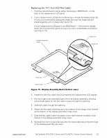
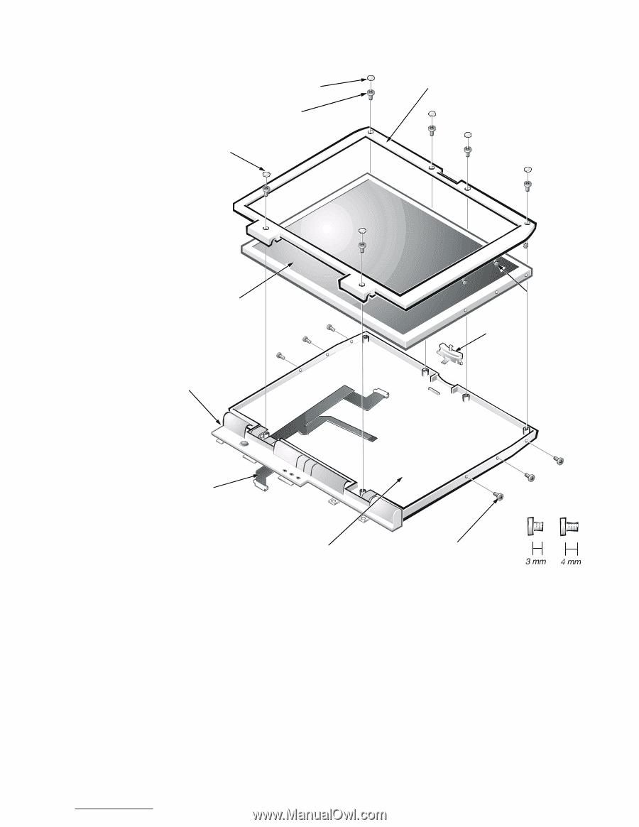
rubber screw covers (4) 4-mm screws (6) plastic screw covers (2) display assembly bezel LCD panel hinge cover plastic tabs (6) bezel latch LCD flex cable display-assembly top cover 3-mm screws (6) M2.0x3 M2.5x4 1. Use a scribe to carefully pry the four rubber screw covers out of the four screw holes located at the top of the bezel on the front of the display assembly. 2. Remove the four 4-mm screws located at the top of the bezel on the front of the display assembly (see Figure 14). support.dell.com Dell Latitude CPt V/CPt S Series and CPx H/CPx J Series Service Manual 21
-
 1
1 -
2
-
3
-
4
-
5
-
6
-
7
-
8
-
9
-
10
-
11
-
12
-
13
-
14
-
15
-
16
-
17
-
18
-
19
-
20
-
21
-
22
-
 23
23 -
 24
24 -
 25
25 -
 26
26 -
 27
27 -
 28
28 -
 29
29 -
 30
30 -
 31
31 -
 32
32 -
 33
33 -
34
-
35
-
36
-
37
-
38
-
39
-
40
-
41
-
42
-
43
-
44
-
45
-
46
-
47
-
48
 |
 |
support.dell.com
Dell Latitude CPt V/CPt S Series and CPx H/CPx J Series Service Manual
21
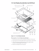
µº¶µ»,Q´K²'LVSOD\²$VVHPEO\²%H]HO²DQG²/&'²3DQHO
O
)LJXUH²µº¶²²µº¶µ»,Q´K²'LVSOD\²$VVHPEO\²%H]HO
5HPRYLQJ±WKH±¶·¸¶µ,Q²K±'LVSOD\±$VVHPEO\±%H]HO
1.
Use a scribe to carefully pry the four rubber screw covers out of the four
screw holes located at the top of the bezel on the front of the display
assembly.
2.
Remove the four 4-mm screws located at the top of the bezel on the front
of the display assembly (see Figure 14).
LCD panel
display-assembly top cover
LCD flex
cable
4-mm screws (6)
bezel
latch
rubber screw covers (4)
plastic screw
covers (2)
3-mm screws (6)
display assembly bezel
hinge cover
M2.0x3
M2.5x4
plastic tabs (6)