Dell Latitude CPx H Service Manual - Page 38
Disconnect the palmrest flex cable from the touch-pad connector on
 |
View all Dell Latitude CPx H manuals
Add to My Manuals
Save this manual to your list of manuals |
Page 38 highlights
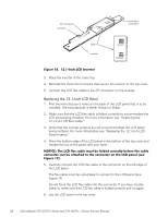
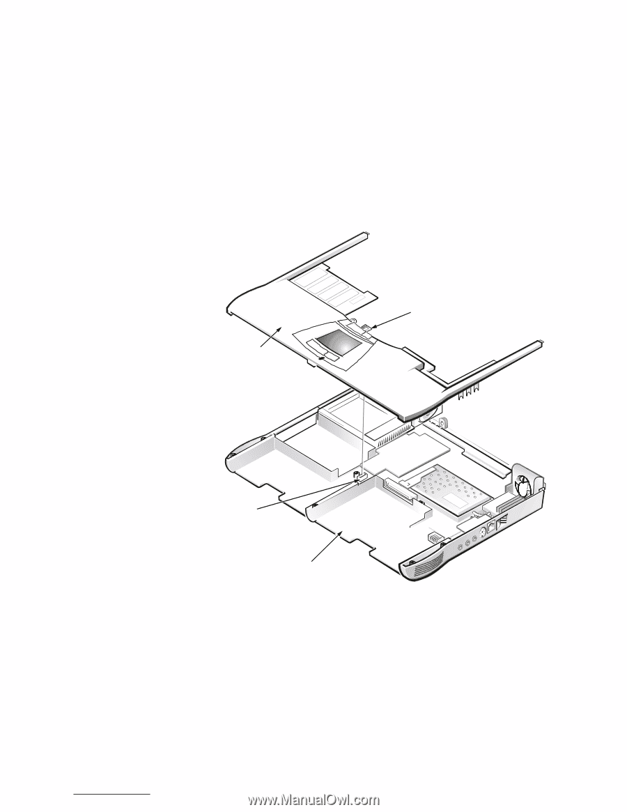
5. Turn the computer upside down on a flat work surface. 6. Remove the five 20-mm screws that secure the palmrest to the computer. These screws, labeled with a " circle P," are located underneath the front edge of the computer (see Figure 19). 7. Turn the computer right-side up on the work surface. 8. Disconnect the palmrest flex cable from the touch-pad connector on the system board (see Figure 20). palmrest assembly palmrest flex cable touch-pad connector bottom case assembly 9. Carefully remove the palmrest assembly from the bottom case assembly (see Figure 20). support.dell.com Dell Latitude CPt V/CPt S Series and CPx H/CPx J Series Service Manual 31
-
 1
1 -
2
-
3
-
4
-
5
-
6
-
7
-
8
-
9
-
10
-
11
-
12
-
13
-
14
-
15
-
16
-
17
-
18
-
19
-
20
-
21
-
22
-
23
-
24
-
25
-
26
-
27
-
28
-
29
-
30
-
31
-
32
-
 33
33 -
 34
34 -
 35
35 -
 36
36 -
 37
37 -
 38
38 -
 39
39 -
 40
40 -
 41
41 -
 42
42 -
 43
43 -
44
-
45
-
46
-
47
-
48
 |
 |
support.dell.com
Dell Latitude CPt V/CPt S Series and CPx H/CPx J Series Service Manual
31
127,&(±²0DNH²VXUH²WKDW²WKH²ZRUN²VXUID³H²LV²³OHDQ²WR²SUHYHQW²V³UDW³Kµ
LQJ²WKH²³RPSXWHU²³RYHU
5.
Turn the computer upside down on a flat work surface.
6.
Remove the five 20-mm screws that secure the palmrest to the computer.
These screws, labeled with a “ circle P,” are located underneath the front
edge of the computer (see Figure 19).
7.
Turn the computer right-side up on the work surface.
8.
Disconnect the palmrest flex cable from the touch-pad connector on the
system board (see Figure 20).
±
)LJXUH²¸Á¶²²3DOPUHVW²$VVHPEO\²5HPRYDO
9.
Carefully remove the palmrest assembly from the bottom case assembly
(see Figure 20).
palmrest assembly
touch-pad
connector
bottom case assembly
palmrest flex cable