Dell Latitude CPx H Service Manual - Page 29
the display-assembly top cover.
 |
View all Dell Latitude CPx H manuals
Add to My Manuals
Save this manual to your list of manuals |
Page 29 highlights
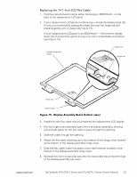
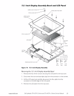
3. Use a scribe to carefully pry the two plastic screw covers out of the two screw holes located at the bottom of the bezel on the front of the display assembly. 4. Remove the two 4-mm screws from the bottom of the bezel. 5. Separate the bezel from the display-assembly top cover. The bezel is secured by three plastic tabs on the left and three plastic tabs on the right side of the display-assembly top cover (see Figure 14). 1. Remove the display assembly bezel. 2. Remove the three 3-mm screws on the left side of the LCD panel and the three 3-mm screws on the right side of the LCD panel (see Figure 14). 3. Lift and rotate the top of the LCD panel out of the top cover. Disconnect the ZIF interface connector and the display-assembly interface cable connector. 4. Lift the LCD panel out of the top cover. 1. Remove the LCD panel. 2. Turn the display assembly upside down on a flat work surface. 3. Remove the 4-mm screw securing the metal cable clip to the left hinge of the display-assembly top cover. 4. Remove the flex cable out from under the plastic strain relief retainer located on the bottom of the display-assembly hinge cover. 5. Remove the flex-cable retaining clip from the bottom of the hinge cover located at the bottom of the display-assembly hinge cover. 6. Pry the hinge-cover assembly apart slightly from the display assembly, allowing just enough space for the flex cable to pass through the opening. 7. Slide the cable through the opening. 22 Dell Latitude CPt V/CPt S Series and CPx H/CPx J Series Service Manual
-
 1
1 -
2
-
3
-
4
-
5
-
6
-
7
-
8
-
9
-
10
-
11
-
12
-
13
-
14
-
15
-
16
-
17
-
18
-
19
-
20
-
21
-
22
-
23
-
 24
24 -
 25
25 -
 26
26 -
 27
27 -
 28
28 -
 29
29 -
 30
30 -
 31
31 -
 32
32 -
 33
33 -
 34
34 -
35
-
36
-
37
-
38
-
39
-
40
-
41
-
42
-
43
-
44
-
45
-
46
-
47
-
48
 |
 |